
Release clutch for a vehicle

a technology for releasing clutches and vehicles, applied in the direction of gearing control, off-road vehicles, portability lifting, etc., can solve the problems of difficult or even impossible to move the vehicle, the propelled device does not drive the clutch, and the ability of the device, so as to achieve the effect of easy vehicle pushing

Inactive Publication Date: 2007-06-26
BRP ROTAX
View PDF17 Cites 10 Cited by
  • Summary
  • Abstract
  • Description
  • Claims
  • Application Information

AI Technical Summary

Benefits of technology

[0008]Accordingly, one aspect of one or more embodiments of this invention provides a vehicle with a simple, inexpensive, reliable, wear-resistant release clutch that makes it easier to push vehicle when the vehicle's engine is not running.
[0009]Another aspect of one or more embodiments of this invention provides a vehicle that includes a propulsion unit, a propelled device, and a continuously variably transmission operatively connecting the propulsion unit to the propelled device. The vehicle also includes a release clutch disposed between the continuously variable transmission and the propelled device. The release clutch has an engaged position and a disengaged position. The release clutch transfers power from the continuously variable transmission to the propelled device when in the engaged position, and prevents the transfer of power from the continuously variable transmission to the propelled device when in the disengaged position. The vehicle also includes a non-centrifugally operated controller. The controller includes an actuator that operates the release clutch. The controller automatically disengages the release clutch when the propulsion unit is not operating.
[0018]Another aspect of one or more embodiments of the present invention provides a vehicle with a release clutch disposed in a drive train between a CVT and a propelled device. The release clutch disengages the CVT from the propelled device when a propulsion unit is not operating. Accordingly, a downstream centrifugal clutch is not required to disengage the CVT form the propelled device. A smaller centrifugal clutch may instead be placed upstream of the CVT between the CVT and the propulsion unit. Such an upstream centrifugal clutch operates at higher speeds and lower torques than conventional downstream centrifugal clutches. Accordingly, the upstream centrifugal clutch can be smaller, less expensive, more wear-resistant, and easier to construct than conventional downstream centrifugal clutches.
[0019]Another aspect of one or more embodiments of the present invention provides a vehicle including a propulsion unit, a propelled device, and a continuously variable transmission operatively connecting the propulsion unit to the propelled device. A release clutch is disposed between the continuously variable transmission and the propelled device. The release clutch has an engaged position and a disengaged position. The release clutch transfers power from the continuously variable transmission to the propelled device when in the engaged position. The release clutch prevents the transfer of power from the continuously variable transmission to the propelled device when in the disengaged position. A controller operatively controls the release clutch. The controller automatically disengages the release clutch when the propulsion unit is not operating and automatically engages the release clutch when the propulsion unit is operating.

Problems solved by technology

The resistance of the gearbox and CVT to such rotation impairs the propelled device's ability to freely move, which makes it very difficult or even impossible to move the vehicle in difficult terrain, particularly if the vehicle itself is heavy.
Consequently, the propelled device does not drive the CVT when the vehicle is being pushed.
Unfortunately, such downstream centrifugal clutches are particularly difficult to design, manufacture, and install because they must operate at the low speeds and high torques that are present downstream from the CVT.
The extreme operating conditions that the centrifugal clutch must endure produce fatigue and wear on the clutch, so that it is impossible to ensure long life and reliability.
Finally, the addition of such a centrifugal clutch complicates assembly of the vehicle and makes the vehicle more expensive.

Method used


Image

  • Release clutch for a vehicle
  • Release clutch for a vehicle
  • Release clutch for a vehicle

Examples


Embodiment Construction

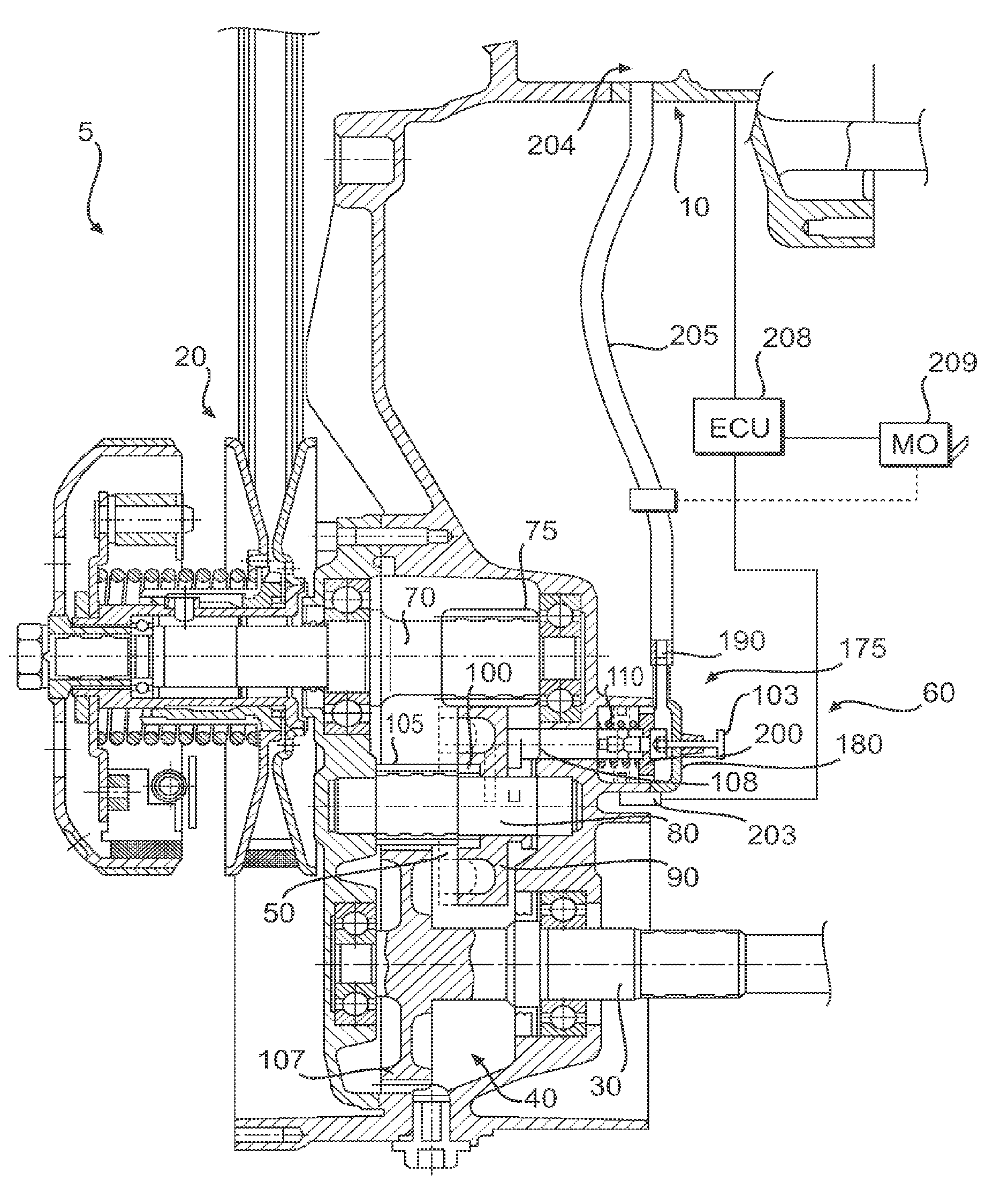
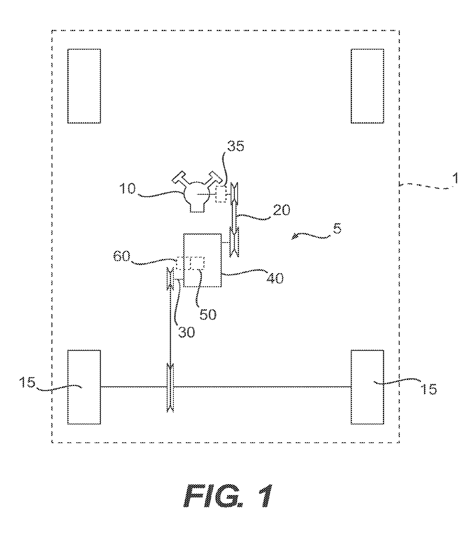
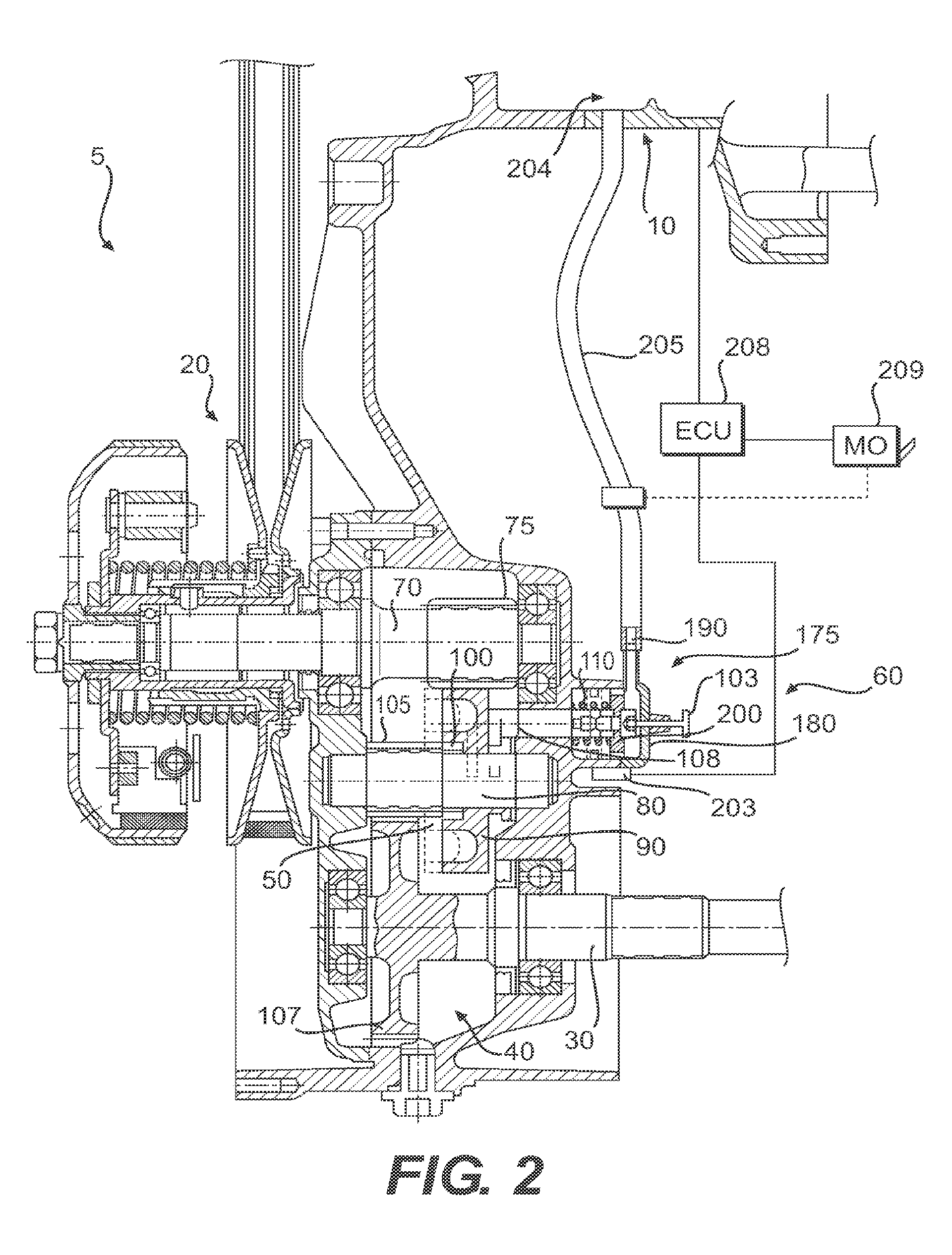
[0025]As shown in FIG. 1, a vehicle 1, which may be any one of a motorcycle, a scooter, a go-kart, an ATV or a snowmobile, includes, among other conventional elements, a drive train 5 that operatively connects a propulsion unit 10 (e.g., an internal combustion engine, motor, etc.) to a propelled device 15 (e.g., wheel(s), an endless track, etc.). As shown in FIGS. 1 and 2, the drive train 5 includes a continuously variable transmission (CVT) 20 operatively disposed between the propulsion unit 10 and a drive shaft 30 for the propelled device 15. A centrifugal clutch 35 is operatively disposed between the propulsion unit 10 and the CVT 20. Toothed gearing 40 is operatively disposed between the CVT 20 and the drive shaft 30. The drive shaft 30 operatively connects to the propelled device 15 to transfer torque from the toothed gearing 40 to the propelled device 15.

[0026]As shown in FIG. 2, the toothed gearing 40 includes a drive shaft 70 that operatively connects to an output end of the...


PUM


Abstract

A vehicle includes an engine that powers a wheel through a drive train. The drive train includes a continuously variable transmission (CVT) and toothed gearing disposed between the CVT and the wheel. A release clutch is also disposed between the CVT and the wheel. A controller controls the release clutch so as to disengage the clutch when the engine is not running and engage the clutch when the engine is running. The controller includes a hydraulic cylinder that fluidly connects to the engine's oil system so that engine-generated oil pressure engages the release clutch. Disengagement of the release clutch makes it easier to push the vehicle when the engine is not running, for example, when the engine breaks down.

Description

CROSS REFERENCE TO RELATED APPLICATIONS[0001]This invention relates to and claims the benefit of priority from U.S. Provisional Application No. 60 / 465,779, filed Apr. 28, 2003, which is hereby incorporated by reference herein in its entirety.BACKGROUND OF THE INVENTION[0002]1. Field of the Invention[0003]This invention relates to drive trains for vehicles, and specifically relates to clutch mechanisms for vehicles that utilize continuously variable transmissions.[0004]2. Description of Related Art[0005]Various recreational vehicles (e.g., motorcycles, scooters, go-karts, all-terrain vehicles (ATVs), snowmobiles, etc.) have drive trains that include continuously variable transmissions (CVTs) to transfer power from a propulsion unit (e.g., an internal combustion engine, electric motor, etc.) to a propelled device (e.g., a wheel(s), an endless track, etc.) to propel the vehicle. Such drive trains also typically include toothed gearing (e.g., additional reduction gears and / or a manually...

Claims


Application Information

Patent Timeline
Patent Type & Authority Patents(United States)
IPC IPC(8): B60W10/02B60K17/02F16D25/00F16D48/06F16H37/02F16H61/662
CPCF16D25/00F16D48/06B60K17/02Y10T477/6237B60Y2200/114B60Y2200/12B60Y2200/126B60Y2200/20B60Y2200/252F16D2500/1022F16D2500/1026F16D2500/10412F16D2500/10481F16D2500/1088F16D2500/3069F16D2500/50891F16D2500/70424F16H37/021F16H61/662Y10S477/906Y10T477/70Y10T477/75B60K41/12B60W10/02B60W10/101B60W30/18B60W2510/0638B60W2710/021
Inventor KORENJAK, NORBERTKUSEL, HEINZ
Owner BRP ROTAX
Learn More