
Automatic loading device for plates to be milled and loading material method thereof

An automatic feeding and milling technology, which is applied to wood processing equipment, mortising machines, slotting machines, etc., can solve the problems of waste of raw materials, unstable floor quality, etc., and achieve cost saving, manpower saving, and stable product quality Effect

Inactive Publication Date: 2010-09-15
苏州伍得人造板设备有限公司
View PDF0 Cites 29 Cited by
  • Summary
  • Abstract
  • Description
  • Claims
  • Application Information

AI Technical Summary

Problems solved by technology

[0007] The invention provides an automatic feeding device for milling boards and a feeding method thereof to solve technical deficiencies such as unstable quality and serious waste of raw materials in the floor production process of the prior art

Method used


Image

  • Automatic loading device for plates to be milled and loading material method thereof
  • Automatic loading device for plates to be milled and loading material method thereof
  • Automatic loading device for plates to be milled and loading material method thereof

Examples


Embodiment 1

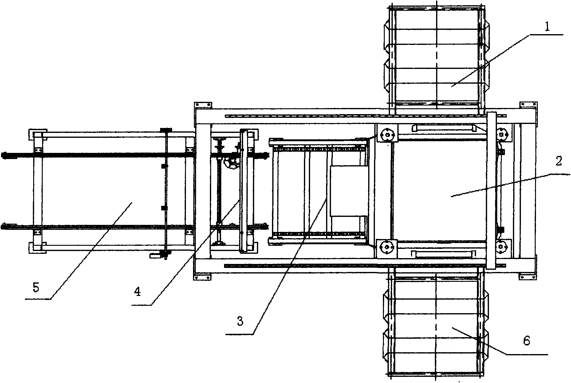
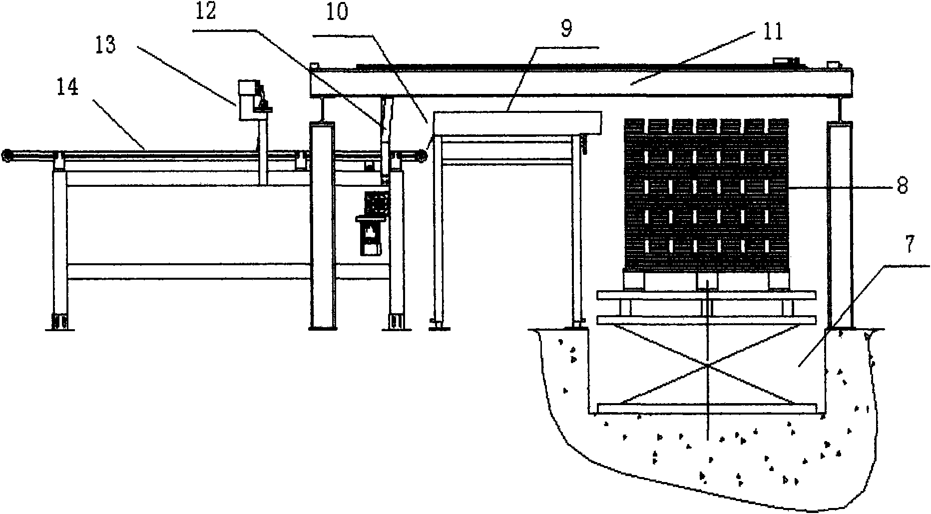
[0082] Use a forklift to move the tray with the semi-finished floor into the loading and unloading conveyor (1). There are forklift slots at the inlet and outlet of the loading and unloading conveyor. The forklift can directly place the pallet on the conveyor table. 2) In the original state, its table surface is slightly lower than the track surface of the loading and unloading conveyor, so that when the hydraulic lifting platform rises, it can jack up the tray. The loading and unloading conveyor adopts chain guide rails, (1) and (6) ends have forklift slots, and the pallet limit column is soft-started by frequency converter to prevent the impact displacement of the floor strips on the pallet. Then the hydraulic lifting steering table is started, and the pallet is jacked up so that the height of the uppermost slab is equal to the table surface of the transition roller table, and the lifting cylinder stops. At this time, the pusher (28) is started by a chain, and pushes the upp...

Embodiment 2

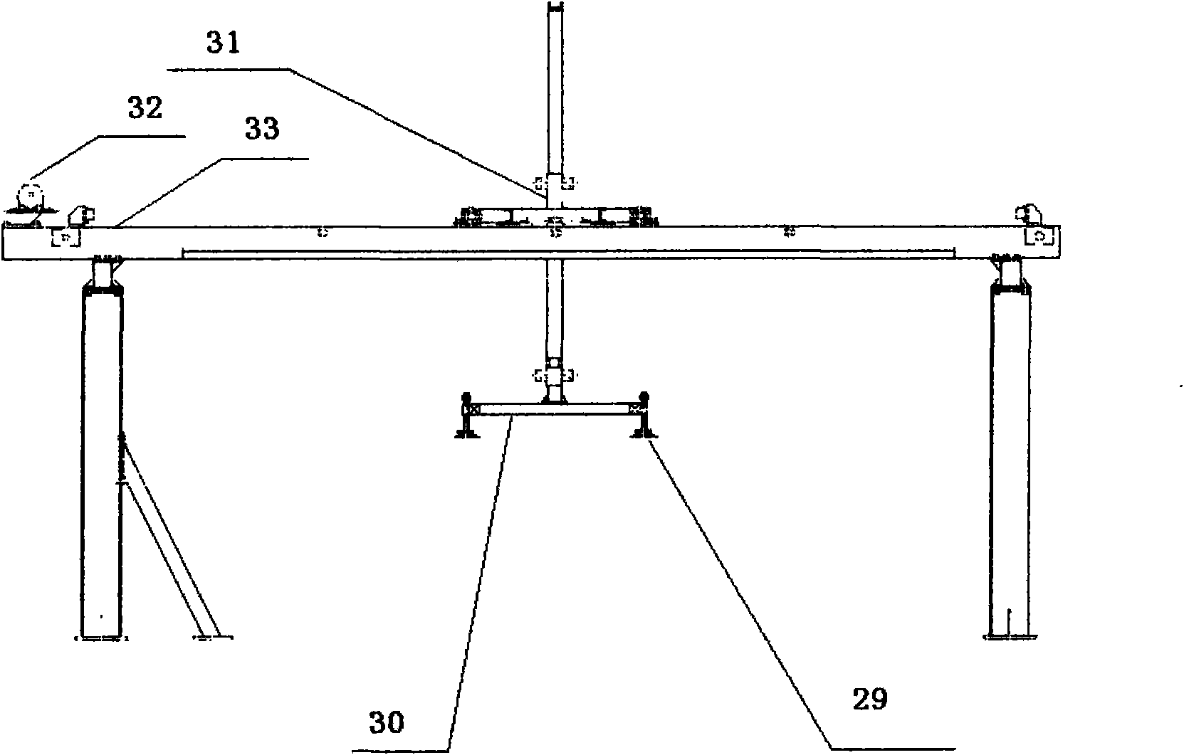
[0087] Use a forklift to move the tray with the semi-finished floor into the loading and unloading conveyor (1). There are forklift slots at the inlet and outlet of the loading and unloading conveyor. The forklift can directly place the pallet on the conveyor table. 2) In the original state, its table surface is slightly lower than the track surface of the loading and unloading conveyor, so that when the hydraulic lifting platform rises, it can jack up the tray. The loading and unloading conveyor adopts chain guide rails, and (1) (6) ends have forklift grooves to prevent the impact displacement of the floor strips on the pallet. Then the hydraulic lifting steering platform is started, and the pallet is lifted up so that the height of the uppermost slab can meet the height requirement of the suction plate sports car, the lifting cylinder stops, and then the suction plate sports car system starts, driven by the suction cup cylinder, the suction cup first descends , and then abso...


PUM


Abstract

The invention discloses an automatic loading device for plates to be milled, which is suitable for delivering wood floor strips in a production process. The device consists of a feeding and discharging conveyor, a hydraulically lifted steering platform, a plate pusher or a plate absorbing carriage system, a lift-up roller and a turning and conveying mechanism, wherein the feeding and discharging conveyor is used for conveying a tray inside and outside; the hydraulically lifted steering platform is used for lifting the tray and steering the tray at an right angle horizontally; the plate pusher is used for pushing a plate blank onto the lift-up roller; the plate absorbing carriage system absorbs the plate blank and transfers the plate blank to the turning and conveying mechanism; and the turning and conveying mechanism turns the designated plate blank. The invention also discloses an automatic loading method for the plates to be milled, which comprises the following steps of: conveying the tray to the feeding and discharging conveyor; transferring the plate blank (lapped in a single manner) on the top layer onto the lift-up roller by using the plate pusher and conveying the plate blank onto the turning and conveying mechanism; or absorbing the plate blank and transferring the plate blank on the turning and conveying mechanism by using the plate absorbing carriage system; and turning over the designated plate blank by using a turning hook and conveying the designated plate blank into a two-end mill. The automatic loading device and the automatic loading method thereof adopt automatic control, are convenient to operate, reduce labor intensity and save materials.

Description

technical field [0001] The invention relates to an automatic feeding device for milling boards and a feeding method thereof, belonging to the field of mechanical equipment of an artificial floor flow production line, especially in the process of floor processing and production, which can transport slabs to double-end milling boards one by one , and the specified slab can be turned over to facilitate later production and protect the slab from wear. Background technique [0002] With the improvement of people's living standards, the requirements for home decoration and building materials are also increasing, and various floors are also emerging in an endless stream. The stability and reliability of floor production quality mainly depends on the quality control in the production process, and every link may affect the quality of floor strips. [0003] In the process of wood floor production, there is a process that needs to plan grooves on both sides of the semi-finished slabs ...

Claims


Application Information

Patent Timeline
Patent Type & Authority Applications(China)
IPC IPC(8): B27F5/02
Inventor 姜伟民
Owner 苏州伍得人造板设备有限公司
Learn More