
Fuel dispensing spout with continuous endface

a technology of end-face and nozzle, which is applied in the direction of pliable tubular containers, liquid handling, packaging goods types, etc., can solve the problems of irritating the nose, throat, lungs, and bringing on asthma attacks, and achieve the effect of reducing the amount of residual fuel

Inactive Publication Date: 2007-06-26
KNUBOX TECH
View PDF28 Cites 23 Cited by
  • Summary
  • Abstract
  • Description
  • Claims
  • Application Information

AI Technical Summary

Benefits of technology

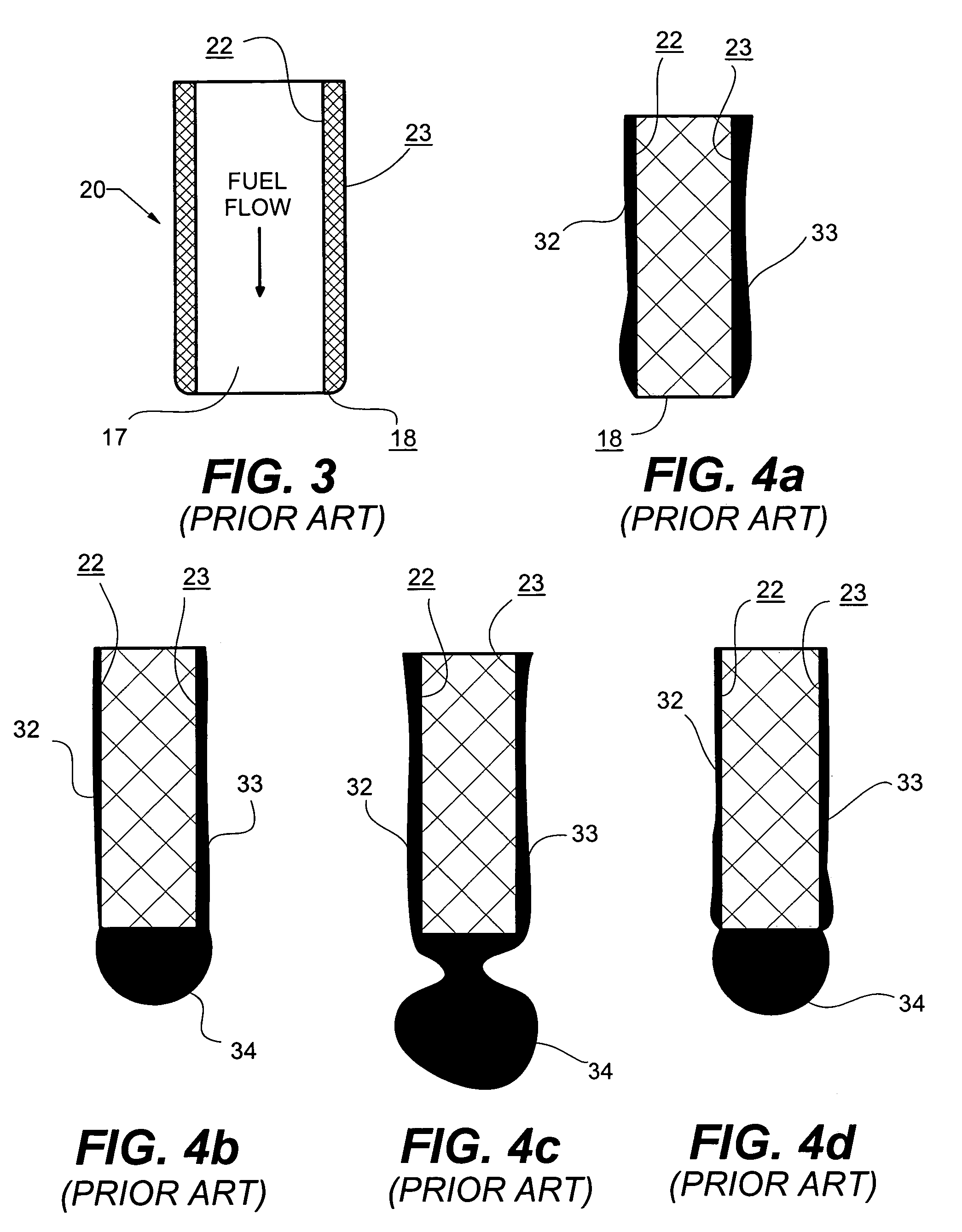
[0013]The present invention therefore aims at providing a nozzle that reduces the amount of residual fuel left on a spout after fueling by encouraging the residual fuel to drip into the container to be filled. A fuel dispensing nozzle is comprised of a nozzle body, a fuel regulating valve, and a spout for directing the fuel supply from the regulating valve to and in the container to be filled. After a fueling cycle, fuel clings to both the inside and outside spout surfaces and can be considered a falling film. Wherein existing nozzle spouts have discontinuous spout endfaces that impede the flow of falling films into the container to be filled, the improved nozzle and endface according to the present invention provides a nozzle spout that promotes fuel drops to form and fall into a container to be filled.

Problems solved by technology

Ground level ozone can potentially cause irritation to the nose, throat, lungs and bring on asthma attacks.
In addition, fuel vapors contain other harmful toxic chemicals, such as benzene.
Although vapor recovery systems can significantly reduce the amount of vapors that reach the atmosphere, the technology is expensive to install and operate, and thus has been implemented in limited areas.
In addition, vapor recovery systems do not address the sources of dripping fuel or residual fuel.
The issues of fuel dripping and residual fuel have largely been either ignored, or inadequately addressed by equipment manufacturers.
Although these valve systems may reduce the amount of drops that occur, they are unlikely to consistently meet the requirements set forth by CARB.
A problem with “dripless” technologies, such as listed above, is that they do not eliminate the drip creating residual fuel from the outside surfaces of the spout.
In addition, the “dripless” features themselves have surfaces that can attract liquid fuel and increase the potential for drops.
Another problem with existing nozzle technologies, such as described above, is that they do not typically work with existing “standard” (non-vapor recovery) type nozzles.
Yet another problem with existing nozzle technologies is that they require significant change-over costs.

Method used


Image

  • Fuel dispensing spout with continuous endface
  • Fuel dispensing spout with continuous endface
  • Fuel dispensing spout with continuous endface

Examples


Embodiment Construction

[0033]Many of the fastening, connection, manufacturing and other means and components utilized in this invention are widely known and used in the field of the invention are described, and their exact nature or type is not necessary for a person of ordinary skill in the art or science to understand the invention; therefore they will not be discussed in detail.

[0034]As used herein, a reference with “′” (prime) indicates that the object is an improved object according to the present invention.

[0035]Applicant hereby incorporates by reference the following U.S. patents: U.S. Pat. No. 5,765,609 for an aluminum fuel spout construction; U.S. Pat. No. 5,603,364 for a “dripless” nozzle; U.S. Pat. No. 4,453,578 for a automatic shut-off nozzle; and, U.S. Pat. No. 5,213,142 for a vapor recovery system.

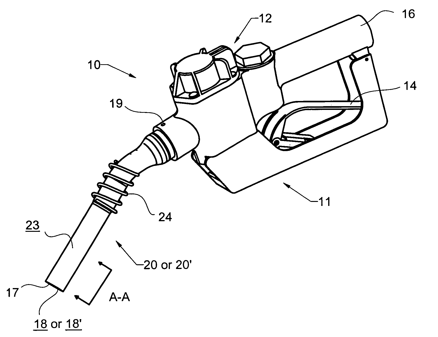
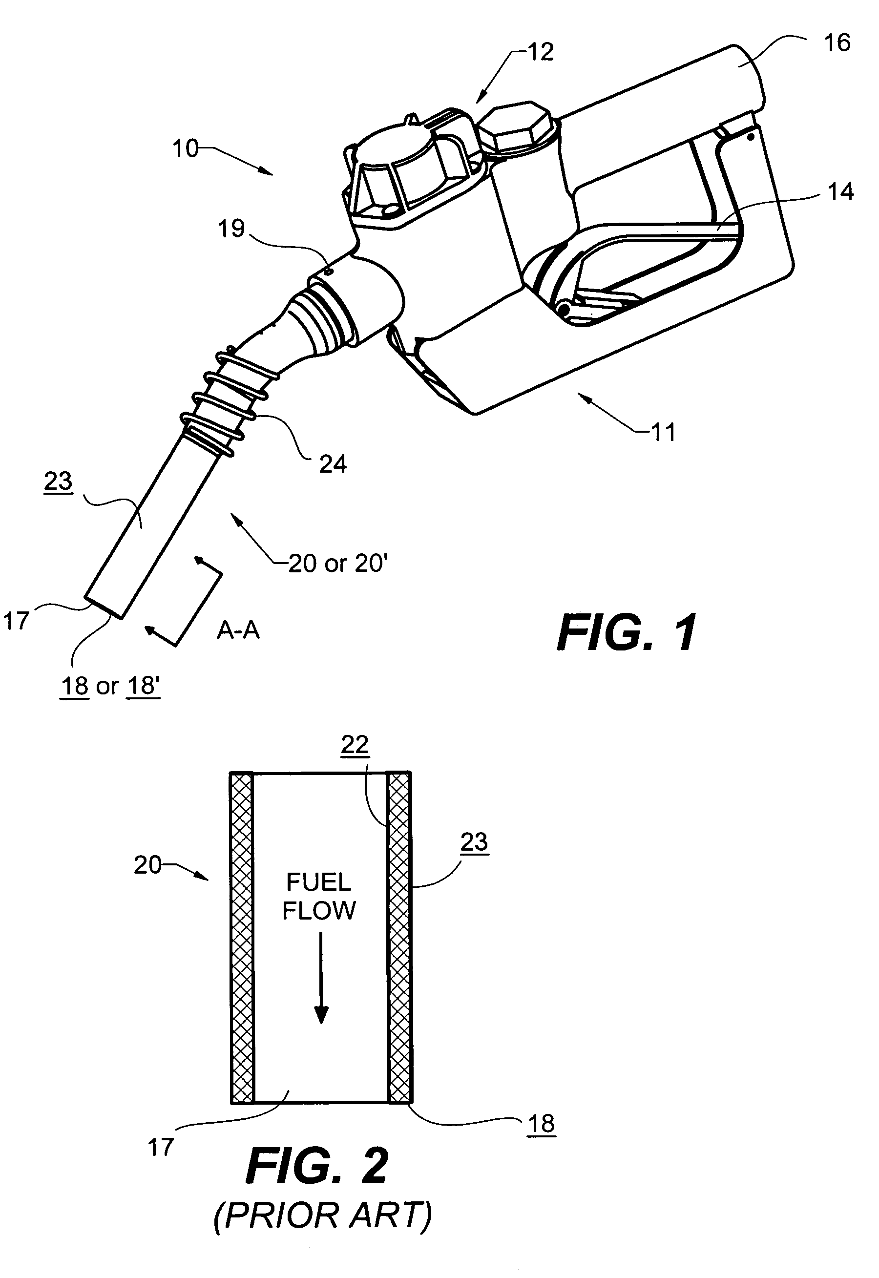
[0036]Referring now to the drawings, FIG. 1 shows a fuel dispensing nozzle assembly 10. Nozzle assembly 10 has an inlet end 16 for receiving a supply of liquid fuel from a hose and pump system (not...


PUM

PropertyMeasurementUnit
Flow rateaaaaaaaaaa

Abstract

The present invention therefore aims at providing a nozzle that reduces the amount of residual fuel left on a spout after fueling by encouraging the residual fuel to drip into the container to be filled. A fuel dispensing nozzle is comprised of a nozzle body, a fuel regulating valve, and a spout for directing the fuel supply from the regulating valve to and in the container to be filled. After a fueling cycle, fuel clings to both the inside and outside spout surfaces and can be considered a falling film. Wherein existing nozzle spouts have discontinuous spout end faces that impede the flow of falling films into the container to be filled, the improved nozzle and endface according to the present invention encourage the falling films to create drops that fall into a container to be filled.

Description

CROSS REFERENCE TO RELATED APPLICATION[0001]There are no related applications.STATEMENT REGARDING FEDERALLY SPONSORED R&D[0002]Not applicable to this application.TECHNICAL FIELD[0003]This invention relates to a fuel nozzle and more particularly to a fuel dispensing nozzle that promotes residual fuel on the nozzle spout to drip into a container to be filled prior to the spout being removed from the container.BACKGROUND OF THE INVENTION[0004]Fuel dispensing nozzles are widely used and understood in the field. Fuel nozzles are used for directing and regulating a flow of fuel into a container to be filled. Typical fuel nozzles are comprised of a nozzle body, a valve assembly for regulating fuel flow, and a tubular spout.[0005]Recently, significant attention has been directed to the adverse environmental effects caused by fuel dispensing nozzles. Fuel nozzles create vapors that contain volatile organics that chemically react with nitrogen oxides to form ground level ozone, often called “...

Claims


Application Information

Patent Timeline
IPC IPC(8): B65D5/72
CPCB67D7/42B67D7/52Y10T137/5762
Inventor KNIGHT, PAUL ALLANTAKISAKI, WALT D
Owner KNUBOX TECH
Learn More