Ball nose cutting insert and ball end mill thereof

a technology of inserts and end mills, which is applied in the field of throwaway, can solve the problems of excessive thinness of the insert body at the flank, unavoidable decrease of flank thickness, and inability to take into account the thickness of the insert body as described above, etc., and achieve satisfactory cutting, stable cutting processing, and reduced cutting resistance

Active Publication Date: 2007-06-05
MITSUBISHI MATERIALS CORP
View PDF7 Cites 13 Cited by
  • Summary
  • Abstract
  • Description
  • Claims
  • Application Information

AI Technical Summary

Benefits of technology

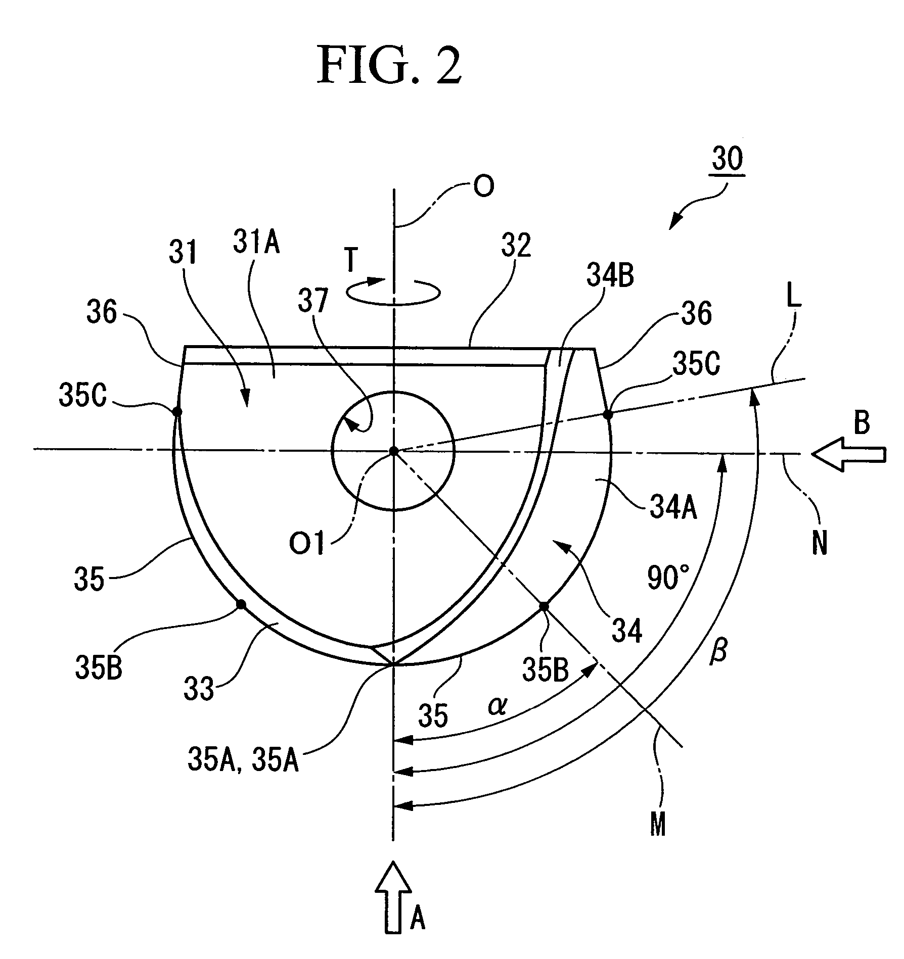
[0011]In the insert of the present invention, when the insert is attached to the insert mounting seat, as a result of the helix angle of the cutting edge twisted about the axis and the thickness of the insert body being set to the ranges as described above, since a comparatively gentle but adequately large helix angle is imparted to the cutting edge, cutting resistance decreases and satisfactory cutting is obtained. In addition, since the thickness of the insert body at the flank on the rear end side of the insert body is not excessively thin, the rigidity of the insert body is adequately secured, thereby enabling stable cutting processing.
[0012]In addition, in the insert of the present invention, the point on the cutting edge that protrudes farthest towards the front in the direction of tool rotation when the insert is attached to the insert mounting seat is preferably located on a straight line that passes through the center of the rough hemisphere formed by the rotational locus of the cutting edge and forms an angle of inclination of 40° to 70° relative to the axis. As a result of employing this constitution, the helix angle of the cutting edge and the thickness of the insert body can be set in proper balance within the ranges described above.
[0013]In addition, in the insert of the present invention, a chamfer formed by cutting away the rear end side of a flank of the insert body towards the rear end surface of the insert body is preferably formed in the insert body. As a result of employing this constitution, a section where the thickness of the insert body becomes particularly thin is eliminated, thereby making it possible to enhance the strength of the insert body.

Problems solved by technology

As a result, the thickness of the flank unavoidably tends to decrease on the rear end side of the insert body.
However, the thickness of the insert body as described above is not taken into consideration at all in the insert disclosed in the aforementioned publication.
Moreover, since the helix angle of the cutting edge is set to an extremely large angle of 20° to 40°, on the rear end side of the insert body, the thickness of the insert body at the flank becomes excessively thin, and as a result, the rigidity of the insert body is unable to be adequately secured, thereby resulting in the possibility of being unable to carry out stable cutting processing.

Method used


Image

  • Ball nose cutting insert and ball end mill thereof
  • Ball nose cutting insert and ball end mill thereof
  • Ball nose cutting insert and ball end mill thereof

Examples


Embodiment Construction

[0019]The following provides an explanation of embodiments of the present invention with reference to the attached drawings.

[0020]As shown in FIG. 1, a tool body 10 of a ball end mill in the present embodiment has a roughly columnar shape centering on axis O, and a groove-shaped insert mounting seat 11 that is indented to the rear end side along axis O is formed in its distal end.

[0021]An insert as shown in FIGS. 2 through 4 is inserted into and attached to insert mounting seat 11. A ball end mill to which an insert is attached cuts a work piece with a cutting edge 35 formed on the insert by moving its tool body 10 in the direction that intersects axis O while rotating towards the front side in the direction of tool rotation T centering on axis O.

[0022]As shown in FIGS. 2 through 4, an insert body 30 of the insert is formed from a hard material such as cemented carbide in roughly the shape of a plate that forms a roughly semicircular shape when viewed from overhead. In the state in ...


PUM


Abstract

In this insert, in addition to the insert being formed so that the cutting edge is twisted at a helix angle within the range of 5° to 25° about the axis when the insert is attached to the insert mounting seat, the thickness of the insert body at the flank located on a straight line, which passes through the center of the rough hemisphere formed by the rotational locus of the cutting edge and forms an angle of inclination of 90° relative to the axis, is set to be within the range of 0.5 D to 0.9 D relative to the thickness D of the rough plate that composes the insert body. As a result, since a comparatively gentle but adequately large helix angle is imparted to the cutting edge, cutting resistance decreases. In addition, since the thickness of the insert body at the flank on the rear end side of the insert body is not excessively thin, the rigidity of the insert body is adequately secured.

Description

BACKGROUND OF THE INVENTION[0001]1. Field of the Invention[0002]The present invention relates to a throwaway insert (to be referred to as an insert) provided with a roughly circular cutting edge removably attached to a throwaway-type ball end mill (to be referred to as a ball end mill).[0003]2. Description of the Related Art[0004]A ball end mill is known in the prior art in which an insert, on which a roughly circular cutting edge is formed on a certain flank on a roughly plate-shaped insert body, is inserted into a groove-shaped insert mounting seat formed on the distal end of a tool body that rotates about an axis, and attached to the insert mounting seat so that the rotational locus of the roughly circular cutting edge about the axis is roughly hemispherical.[0005]As disclosed in, for example, Japanese Unexamined Patent Application, First Publication No. 4-146015, one example of an insert used in this type of ball end mill consists is that in which, when the tool body in which th...

Claims


Application Information

Patent Timeline
Patent Type & Authority Patents(United States)
IPC IPC(8): B23C5/20
CPCB23C5/1036B23C2210/0485Y10T407/1948Y10T407/1924Y10T407/1936B23C2210/084
Inventor TSUCHITANI, MASAYASHIMOMURA, HIROSHIOKAZAKI, YASUTAKA
Owner MITSUBISHI MATERIALS CORP
Why Eureka
Try Eureka