Methods and apparatus for delay free phase shifting in correcting PLL phase offset

a delay-free phase and offset technology, applied in pulse transformers, pulse techniques, instruments, etc., can solve the problems of signal loss and significant errors, delay and linear filtering frequency sensitive errors, and the system performance is affected by the system

Inactive Publication Date: 2007-05-29
HONEYWELL INT INC
View PDF18 Cites 4 Cited by
  • Summary
  • Abstract
  • Description
  • Claims
  • Application Information

AI Technical Summary

Benefits of technology

[0006]In one aspect, an apparatus is provided which eliminates a generally frequency dependent differential phase shift, Δθ(f), between a double sideband suppressed carrier modulated angular rate information signal and its sinusoidal demodulation reference signal in a gyroscope angular rate sensing circuit. The rate sensing circuit includes a demodulation reference source. The apparatus comprises a demodulator, a PLL that provides the actual demodulating signal, a phase shift command source, and a phase shifter in a demodulation reference signal path. The PLL comprises a phase detector, a servo equalizer, and a dual-frequency numerically controlled oscillator (NCO). The demodulation reference signal path is between the demodulation reference source and the phase detector because the actual demodulating signal is the PLL output. The phase shifter is configured to adjust a phase of the sinusoidal demodulation reference signal and the phase shift command source is configured to provide an input to the phase shifter to command an appropriate phase adjustment.
[0007]In another aspect, a method for eliminating a differential phase shift, Δθ(f), between a double sideband suppressed carrier modulated information signal and its sinusoidal demodulation reference signal in a circuit is provided. The circuit includes a demodulator, a phase shift command source and a phase shifter...

Problems solved by technology

However, in certain applications, the phase difference is frequency-sensitive and the frequency of operation is not exactly known, resulting in a phase error which can deleteriously effect the performance of the system in which the PLL is a component.
Specifically, in digital gyroscope applications, a frequency sensitive error due both to delays and linear filtering is known to exist.
The two signals are routed along different paths within a gyroscope angular rate sensing system and therefore are subject to both intentional and unin...

Method used


Image

  • Methods and apparatus for delay free phase shifting in correcting PLL phase offset
  • Methods and apparatus for delay free phase shifting in correcting PLL phase offset
  • Methods and apparatus for delay free phase shifting in correcting PLL phase offset

Examples


Embodiment Construction

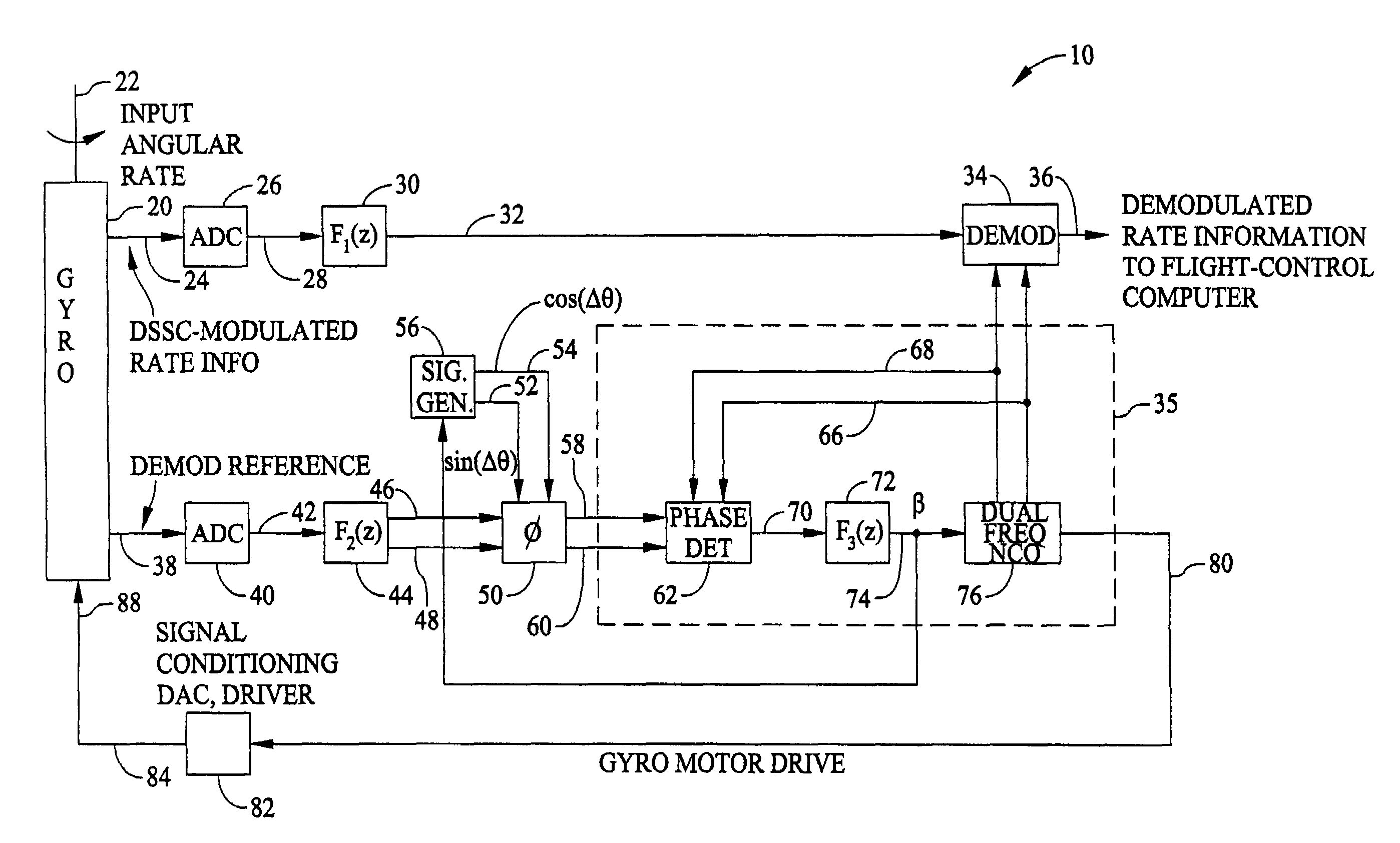
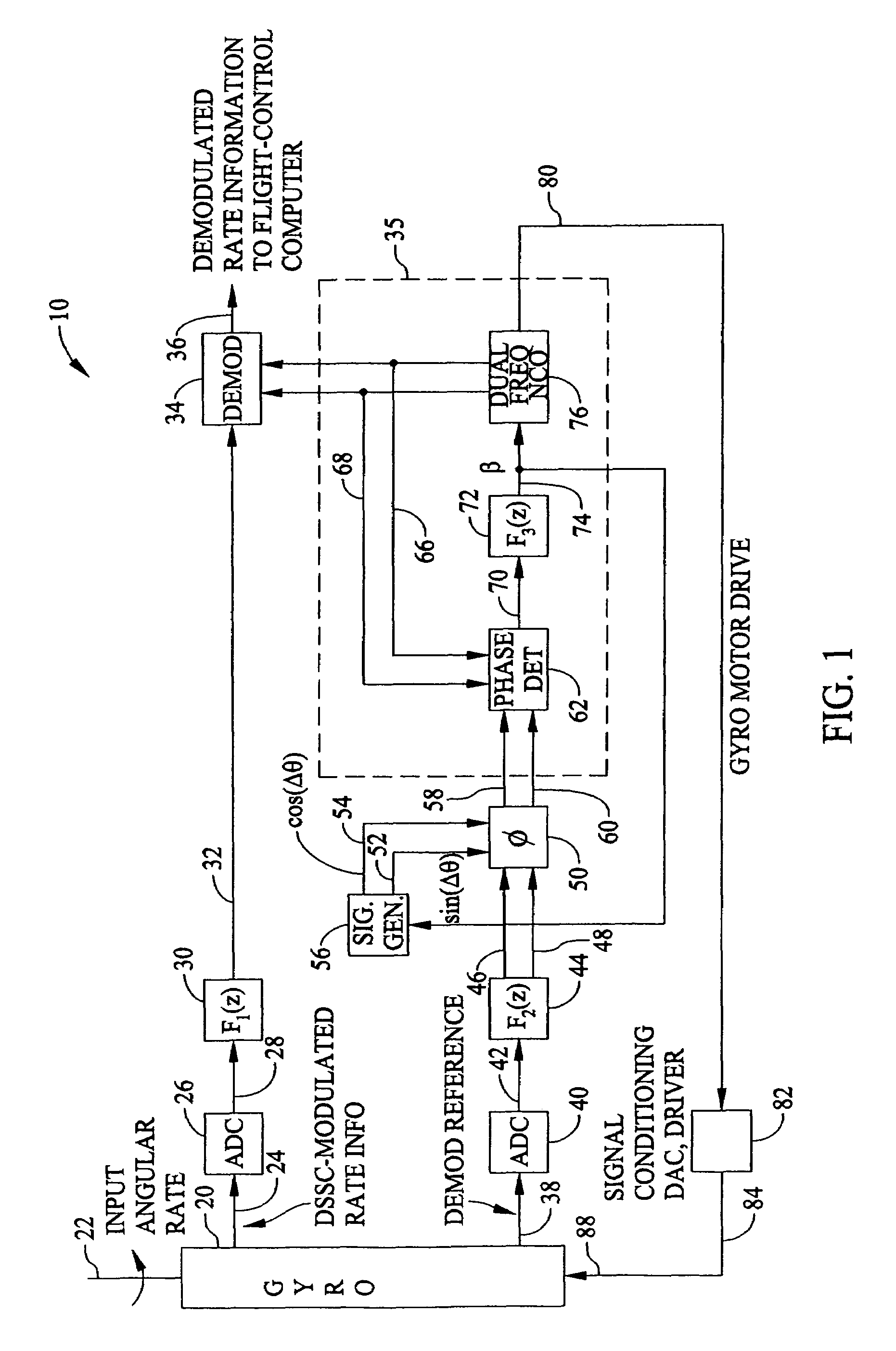
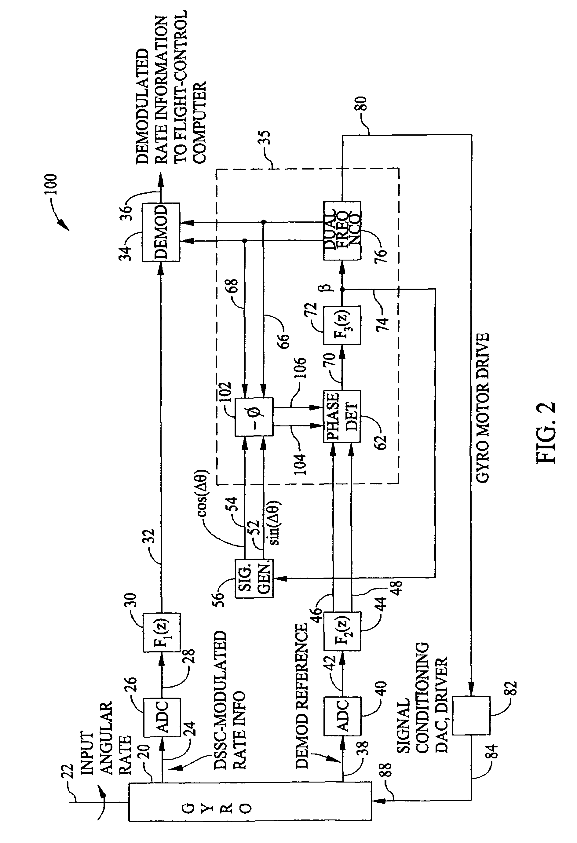
[0014]In the embodiments herein described, differential phase shift is substantially eliminated between a double sideband suppressed carrier (DSSC) modulated angular rate information signal and a demodulation reference signal by inserting a delay-free phase shifter circuit in a signal path of the demodulation reference signal. The demodulation reference signal drives a phase-locked loop (PLL) which outputs very high quality sinusoidal and cosinusoidal outputs which are utilized as demodulating signals. The PLL also provides half-frequency motor-drive signals. By placing a phase shifter in one of the signal paths to the phase detector of the PLL, phase control of a very high quality is achieved. A delay-free phase shifter for sinusoidal and cosinusoidal signals is obtained by direct mechanization of the expansion formula for the sine and the cosine of the sum of two angles, i.e., sin(x+y)=sin(x)cos(y)+cos(x)sin(y) and cos(x+y)=cos(x)cos(y)−sin(x)sin(y).

[0015]As described below, the p...


PUM


Abstract

An apparatus eliminates a differential phase shift, Δθ(f), between a double sideband suppressed carrier modulated angular rate information signal and its sinusoidal demodulation reference signal in a gyroscope angular rate sensing circuit including a signal reference source. The apparatus includes a demodulator, a phase shifter in a demodulation reference signal path, the demodulation reference signal path being between the signal reference source and the demodulator. The phase shifter is configured to adjust a phase of the sinusoidal demodulation reference signal. A phase locked loop (PLL) includes a phase detector, a servo equalizer, and a dual-frequency, numerically controlled oscillator. The PLL is configured to provide a demodulation signal based on the phase shifted demodulation reference signal, and a phase shift command source is configured to provide an input to the phase shifter to command an appropriate phase adjustment.

Description

BACKGROUND OF THE INVENTION[0001]This invention relates generally to digital signal processing (DSP) and, more specifically, to methods and apparatus for the demodulation of a digitized first information bearing signal by a digitized second demodulation reference signal.[0002]A phase-locked loop (PLL) generates an output waveform, such as a sinusoid, that is intended to be locked in both frequency and phase to a reference waveform. The purpose of the PLL action is to synchronize the PLL output waveform with that of an input reference waveform. Depending upon the application, the requirement may be to lock on an input-reference source waveform, or a phase-modified received waveform. However, if the received waveform has been filtered or delayed subsequent to its generation, the PLL output signal will be synchronized with the received signal, but not with the source signal. If the phase difference between the source and received waveforms is small, there may be little consequence. Fur...

Claims


Application Information

Patent Timeline
IPC IPC(8): H04L7/00H04L25/00H04L25/40G01C19/42G01C19/5649H03L7/081H03L7/23
CPCG01C19/42G01C19/5649H03L7/081E05Y2400/30H03L7/235
Inventor WHITE, STANLEY A.
Owner HONEYWELL INT INC
Why Eureka
Try Eureka