Electronic timepiece

a technology of electronic timepieces and timepieces, applied in the field of electronic timepieces, can solve the problems of unstable antenna characteristics, low reception performance, and unstable antenna frequency shifting, and achieve the effects of preventing damage to ceramic dielectric substrates, improving the positioning precision of planar antennas to the base plate, and improving the accuracy of planar antenna positioning

Active Publication Date: 2018-02-06
SEIKO EPSON CORP
View PDF19 Cites 2 Cited by
  • Summary
  • Abstract
  • Description
  • Claims
  • Application Information

AI Technical Summary

Benefits of technology

[0010]Because a through-hole that overlaps the antenna electrode of the planar antenna in plan view is formed in the base plate, less of the base plate or dielectric is in proximity to the antenna electrode when the planar antenna is placed close to the base plate than when a through-hole is not formed, the shift in the antenna frequency can be reduced, and antenna performance can be stabilized. Furthermore, because the planar antenna can be located near the base plate, the movement that houses the planar antenna can also be made thinner, and an electronic timepiece having the movement can be made thinner.
[0021]The solar panel includes electrodes, but because the solar panel and the planar antenna do not overlap each other in plan view in the invention, radio waves passing from the face side of the timepiece are picked up by the antenna without being obstructed by the solar panel. A solar panel can therefore be provided in the electronic timepiece without reducing reception performance.

Problems solved by technology

Because the base plate is a dielectric, however, a new problem of the antenna frequency shifting occurs if the gap between the base plate and the antenna electrode is too small.
The problem becomes particularly acute if this gap is 0.5 mm or less because the frequency shift increases with even the slightest change in the gap between the base plate and the antenna electrode, reception performance drops, and antenna characteristics are not stable.
As a result, movement of the planar antenna to the base plate side can be limited by the exposed surface directly or indirectly contacting the cover part.

Method used


Image

  • Electronic timepiece
  • Electronic timepiece
  • Electronic timepiece

Examples


Embodiment Construction

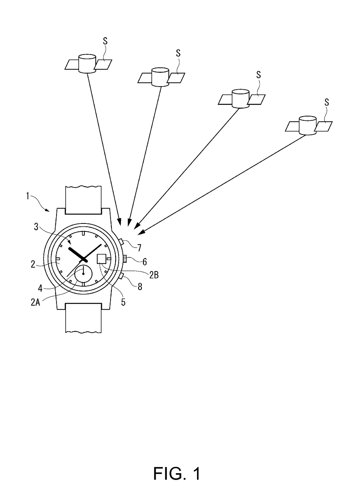
[0033]A preferred embodiment of the present invention is described below with reference to the accompanying figures. Note that the crystal 31 side of the electronic timepiece 1 according to this embodiment of the invention is also referred to as the face, front, or top side, and the back cover 12 side is also referred to as the back or bottom side of the electronic timepiece 1.

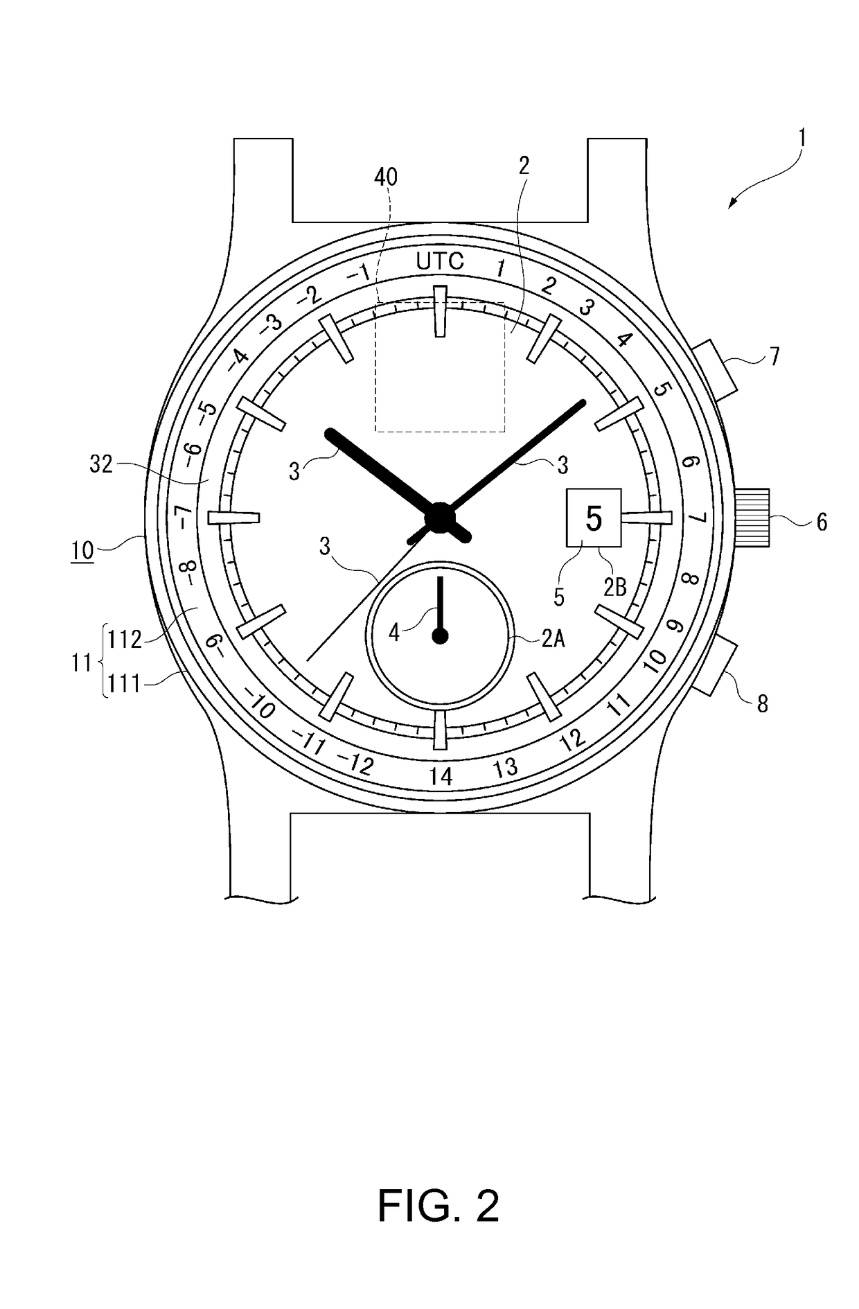
[0034]As shown in FIG. 1 and FIG. 2, the electronic timepiece 1 is a wristwatch with a time display unit for displaying the time using a dial 2 and hands 3, an information display unit including a subdial 2A of the dial 2 and a hand 4, and a calendar display unit including a window 2B in the dial 2 and a date wheel 5.

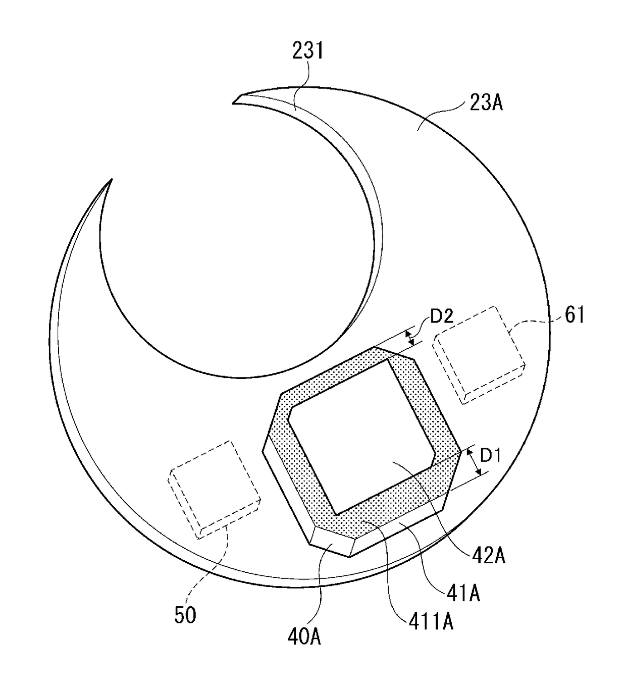
[0035]The dial 2 is a disc-shaped member made of polycarbonate or other non-conductive material. The subdial 2A is located at 6:00 on the dial 2, and the window 2B is located at 3:00 on the dial 2. In addition to the subdial 2A and window 2B, the dial 2 has a through-hole 2C through which the cent...


PUM


Abstract

An electronic timepiece has a base plate made from a non-conductive material, and a planar antenna disposed on the back side of the base plate. The planar antenna has a dielectric substrate and an antenna electrode disposed to the base plate side of the dielectric substrate. An exposed area not superimposed with the antenna electrode 42 is formed on the surface of the dielectric substrate. The base plate has a through-hole overlapping at least part of the antenna electrode in plan view, and a cover part overlapping at least part of the exposed surface in plan view.

Description

BACKGROUND[0001]1. Technical Field[0002]The present invention relates to an electronic timepiece, and relates more particularly to an electronic timepiece with a planar antenna.[0003]2. Related Art[0004]JP-A-2012-13627 describes an electronic timepiece with a planar antenna for receiving radio frequency signals transmitted from GPS (Global Positioning System) or other types of positioning information satellites.[0005]The electronic timepiece in JP-A-2012-13627 has a planar antenna disposed on the back cover side of the dial, and suppresses loss of antenna sensitivity by separating the planar antenna from the metal case around the antenna.[0006]Disposing the planar antenna closer to the base plate that is also disposed on the back cover side of the dial is desirable to make the electronic timepiece thinner. Because the base plate is made of plastic or other non-conductive material, the base plate does not interfere with radio waves, and the planar antenna can receive radio signals ev...

Claims


Application Information

Patent Timeline
Patent Type & Authority Patents(United States)
IPC IPC(8): G04R60/00G04R60/12G04R60/10G04R60/02G04R60/06G04B19/247G04R20/04G04B19/24H01Q1/38
CPCG04B19/24G04B19/247G04R20/04G04R60/02G04R60/10G04R60/12G04R60/00H01Q1/38
Inventor FUJISAWA, TERUHIKO
Owner SEIKO EPSON CORP
Why Eureka
Try Eureka