MEMS vibrator, method of manufacturing MEMS vibrator, electronic device, and moving object
a technology of mems vibrator and electronic device, which is applied in the direction of microstructural devices, instruments, coatings, etc., can solve the problems of fluctuation or reduction in and achieve the effect of reducing the q value of the mems vibrator and high reliability
- Summary
- Abstract
- Description
- Claims
- Application Information
AI Technical Summary
Benefits of technology
Problems solved by technology
Method used
Image

Examples
first embodiment
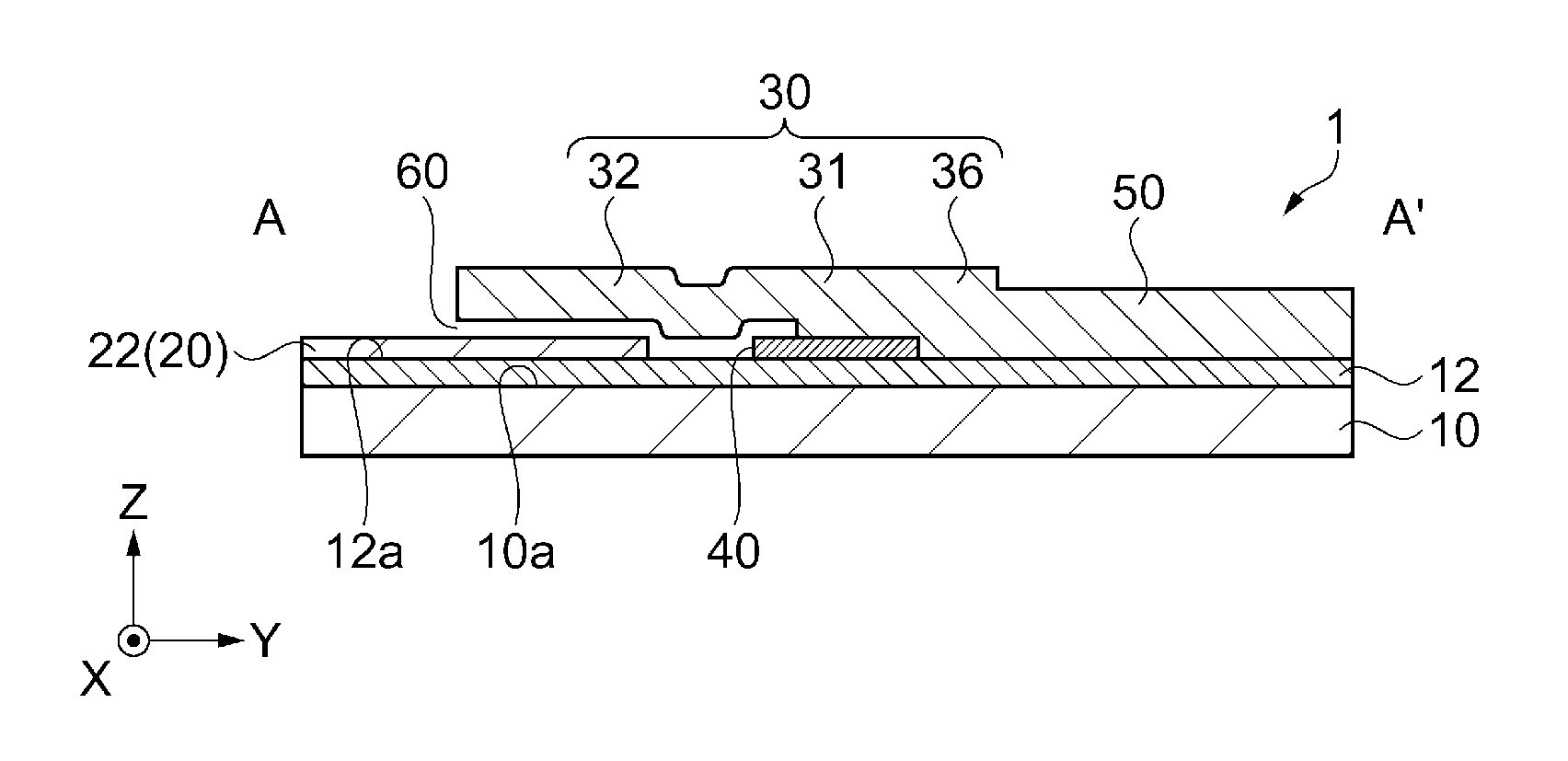
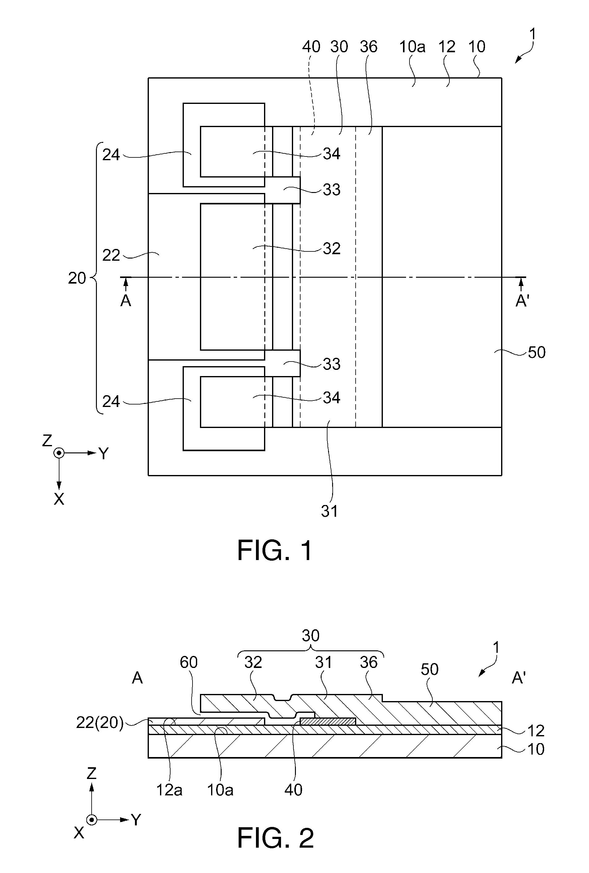
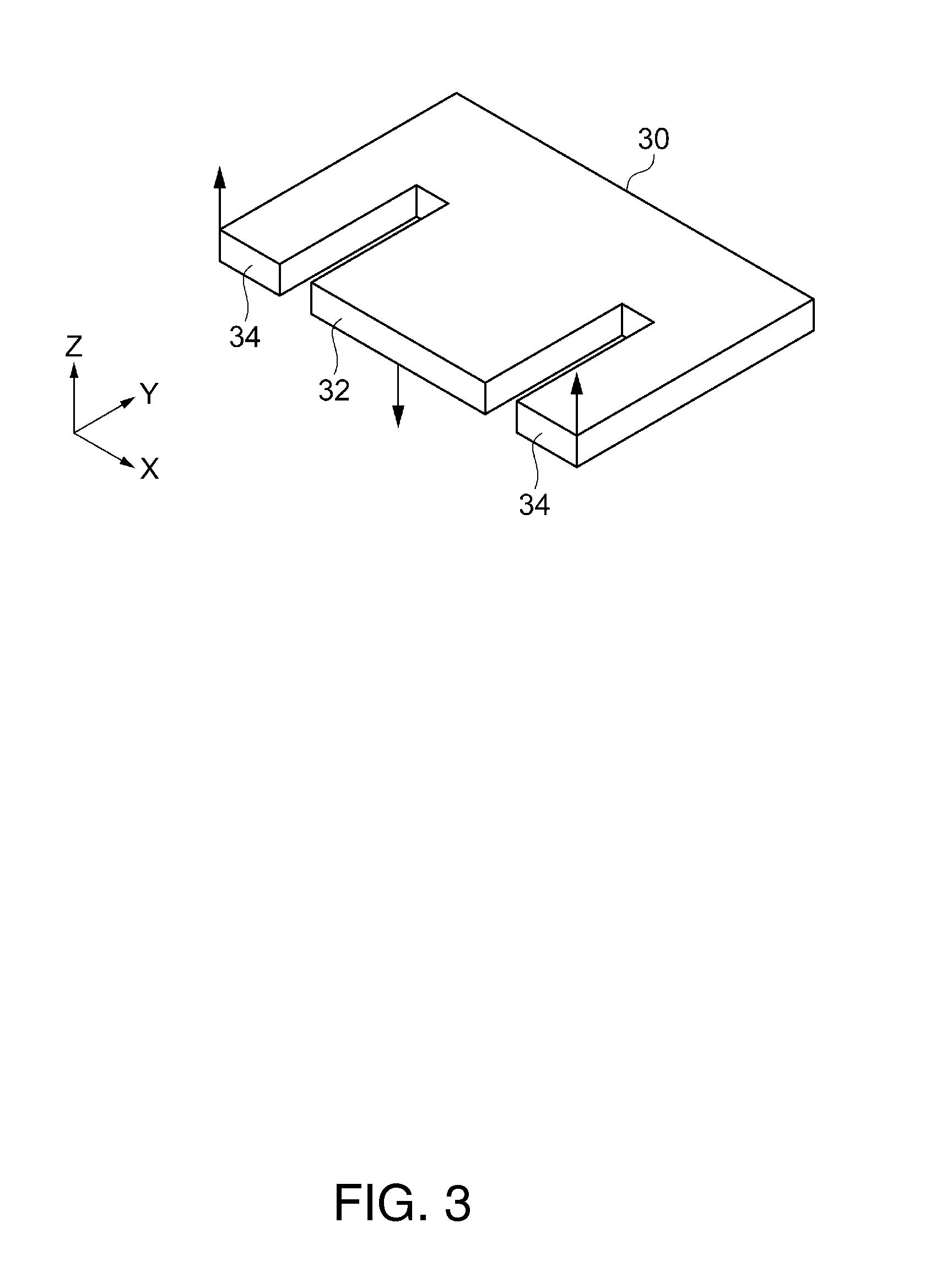
[0044]A MEMS vibrator according to a first embodiment will be described with reference to FIGS. 1 to 5.
[0045]FIG. 1 is a plan view schematically illustrating an outline of the MEMS vibrator according to the first embodiment. FIG. 2 is a cross-sectional view schematically illustrating a cross-section of the MEMS vibrator taken along line A-A′ of FIG. 1. FIG. 3 is a perspective view illustrating an operation of the MEMS vibrator. FIGS. 4A to 5G are diagrams schematically illustrating the cross-section of the MEMS vibrator taken along line A-A′ of FIG. 1, and cross-sectional views illustrating a process of manufacturing the same.
[0046]In addition, FIGS. 1 to 5 illustrate an X axis, a Y axis, and a Z axis as three axes which are at right angles to each other. Meanwhile, the Z axis is an axis indicating a thickness direction in which each electrode is laminated on a substrate.
Structure of MEMS Vibrator1
[0047]A MEMS vibrator 1 according to the first embodiment is a MEMS vibrator of a so-c...
second embodiment
[0117]A MEMS vibrator according to a second embodiment will be described with reference to FIGS. 6A to 101.
[0118]FIGS. 6A and 6B are a plan view and a cross-sectional view, respectively, schematically illustrating the MEMS vibrator according to the second embodiment. FIG. 7 is a cross-sectional view of the MEMS vibrator illustrating an operation of the MEMS vibrator according to the second embodiment. FIGS. 8A to 101 are diagrams schematically illustrating a cross-section of the MEMS vibrator taken along line A1-A1′ of FIG. 6A, and are cross-sectional views illustrating a process of manufacturing a MEMS vibration element of the embodiment.
[0119]In addition, FIGS. 6A to 101 illustrate an X axis, a Y axis, and a Z axis as three axes which are at right angles to each other. Meanwhile, the Z axis is an axis indicating a thickness direction in which the substrate and each electrode are laminated.
Structure of MEMS Vibrator 2
[0120]A MEMS vibrator 2 according to the second embodiment is a M...
example
[0196]Next, an example in which any of the MEMS vibrator 1 and the MEMS vibrator 2 (hereinafter, described as the MEMS vibrator 1 collectively) according to the embodiments of the invention is applied will be described with reference to FIGS. 11 to 14.
Electronic Device
[0197]First, electronic devices to which the MEMS vibrator 1 according to the embodiment of the invention is applied will be described with reference to FIGS. 11 to 13.
[0198]FIG. 11 is a perspective view illustrating an outline of a configuration of a notebook-type (or mobile-type) personal computer as an electronic device including the MEMS vibrator according to the embodiment of the invention. In the drawing, a notebook-type personal computer 1100 is constituted by a main body 1104 including a keyboard 1102 and a display unit 1106 including a display portion 1008, and the display unit 1106 is rotatably supported with respect to the main body 1104 through a hinge structure. Such a notebook-type personal computer 1100 ...
PUM
| Property | Measurement | Unit |
|---|---|---|
| distance | aaaaa | aaaaa |
| thickness | aaaaa | aaaaa |
| vibration frequency | aaaaa | aaaaa |
Abstract
Description
Claims
Application Information
 - R&D
- Intellectual Property
- Life Sciences
- Materials
- Tech Scout
- Unparalleled Data Quality
- Higher Quality Content
- 60% Fewer Hallucinations
Browse by: Latest US Patents, China's latest patents, Technical Efficacy Thesaurus, Application Domain, Technology Topic, Popular Technical Reports.
© 2025 PatSnap. All rights reserved.Legal|Privacy policy|Modern Slavery Act Transparency Statement|Sitemap|About US| Contact US: help@patsnap.com