Micro-actuator, head gimbal assembly and manufacturing method thereof

a micro-actuator and head gimbal technology, applied in the direction of magnetic recording, data recording, instruments, etc., can solve the problems of difficult manufacturing of micro-actuators, low production efficiency, and low production efficiency of micro-actuators, so as to improve the shock performance of micro-actuators, reduce operating voltage, and facilitate salvage and recycling

Inactive Publication Date: 2007-05-15
SAE MAGNETICS (HK) LTD
View PDF42 Cites 6 Cited by
  • Summary
  • Abstract
  • Description
  • Claims
  • Application Information

AI Technical Summary

Benefits of technology

[0020]Compared with the traditional ceramic U-shaped frame, the micro-actuator of the present invention provides a new design of the support base made of metal. Using the metal support base will greatly improve the shock performance of the micro-actuator and solve the problem of generating dust particles.
[0022]The invention is also better for the particle contamination control in the manufacturing process. In addition, the traditional polishing cleaning method can be used for the cleaning process of the present invention. Furthermore, because the ACF bonding is used for slider mounting, it makes the grounding process much easier, and the ACF is easy to salvage and recycle. Finally, the present invention can also reduce the voltage of operating the thin film PZT micro-actuator and achieve the same displacement as the prior art micro-actuator.

Problems solved by technology

However, Because of the inherent tolerance (dynamic play) resulting from VCM that exists in the placement of the slider 203, the slider 203 can not attain a position fine adjustment.
However, a head gimbal assembly (HGA) 277 (see FIG. 1c) with the micro-actuator 205 is very difficult to manufacture.
First, inserting and bonding the slider 203 to the micro-actuator 205 is difficult.
Secondly, the epoxy dot 212 is very difficult to control, if the length of the epoxy dot 212 is too long, it will affect the work performance of the micro-actuator 205, for example, the displacement is not enough; if the length of the epoxy dot 212 is too short, the bonding strength will not be enough and then the shock performance is poor.
Also, because the U-shaped frame 297 of the micro-actuator 205 is very brittle, it has a poor shock performance.
In addition, it is also a big problem that there is no effective method to identify potential micro cracks of the U-shaped frame 297.
Both will influence the static attitude of the HGA 277 and accordingly increase the difficulty of manufacturing the HGA 277.
However, this cleaning method cannot be used in the above-mentioned HGA 277 because it is easy to damage the U-shaped frame 297 of the micro-actuator 205.
Also, it is a waste of energy that a bigger drive voltage (40V, AC p—p) is required for operate the PZT micro-actuator 205.

Method used


Image

  • Micro-actuator, head gimbal assembly and manufacturing method thereof
  • Micro-actuator, head gimbal assembly and manufacturing method thereof
  • Micro-actuator, head gimbal assembly and manufacturing method thereof

Examples


embodiment 1

[0046]Referring to FIG. 5, the manufacturing process of the support base 302 comprises the following steps: (1) die punching a stainless steel sheet 603 to a single unit T-shaped support base; (2) fixing the single unit T-shaped support base to a cutting fixture and cutting it to single T-shaped support bases 302; and (3) cleaning and inspecting the single T-shaped support bases 302.

[0047]In the embodiment, a tooling die 601 with a multi-unit T-shaped support base cutter 602 is used to punch the stain steel sheet 603, after punching, the sheet 603 is made into a sheet frame with many single unit T-shaped support base 302, the sheet frame is then cut into a single bar 605 and then separated into single T-shaped support bases 302.

[0048]FIG. 6 shows another tooling die 701 with a multi-unit T-shaped support base cutter 702, which is used to punch the stainless steel sheet 703. After punching, the sheet 703 is made into a sheet frame with many single unit T-shaped support bases 705, and...

embodiment 2

[0049]Referring to FIG. 7, another manufacturing process of the support base 302 comprises the following steps: (1) fixing a stainless steel sheet 901 and then laminating a spacer 902 on the stainless steel sheet 901; (2) laminating a second stainless steel sheet 903 on the spacer 902; (3) laminating a second spacer on the second stainless steel sheet; (4) repeating the above-mentioned steps until attaining a multi layer unit 904; (5) fixing the multi layer unit 904 to a suitable fixture and cutting the multi layer unit 904 by laser or x-ray 905 into T-shaped multi layer units 906; (6) removing the spacer and the T-shaped multi layer units 906 are automatically separated into single support bases 302; and (7) cleaning and inspecting the single support bases 302.

embodiment 3

[0050]Referring to FIG. 8, another manufacturing process of the support base 302 comprises the following steps: (1) molding a bulk of T-shaped support base bars 501; (2) cutting the T-shape support base bar 501 into single support bases 302 from the T-shaped support base bar 501 by a mechanical method or machining; and (3) separating the support bases 302 from the T-shaped support base bar 501.

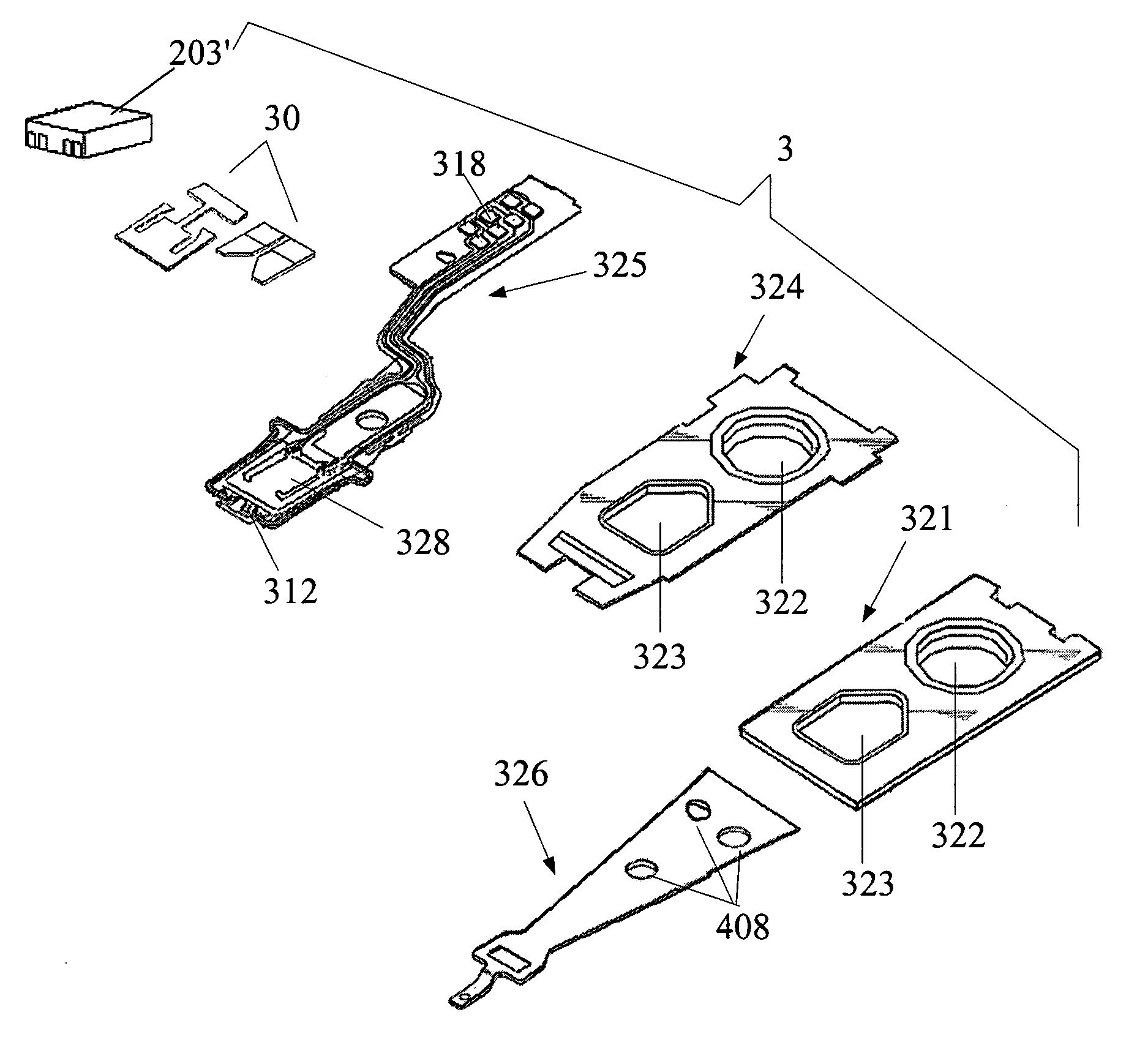
[0051]Referring to FIGS. 9–12, in the present invention, the support base 302 can be the support bases with other shapes 302′, 302″, 302′″ or 302″″, and accordingly be made into micro-actuators with different shapes.

[0052]In the present invention, because a process of assembling the micro-actuator and HGA is well known to persons ordinarily skilled in the art, a detailed description of such assembly is omitted herefrom. In addition, the thin film PZT pieces 303 can also be ceramic PZT pieces.


PUM

PropertyMeasurementUnit
drive voltageaaaaaaaaaa
lengthaaaaaaaaaa
horizontal movementaaaaaaaaaa

Abstract

A head gimbal assembly comprising a slider having a read\write sensor; a suspension to load the slider; a micro-actuator; wherein the micro-actuator comprises a piezoelectric unit with two piezoelectric elements and a support base having a base to be coupled with the suspension physically, a moving plate to be coupled with the two piezoelectric elements, and a leading beam to connect with the base and the moving plate. Also disclosed is a micro-actuator comprising inter alia a piezoelectric unit with two piezoelectric elements. A method of forming a micro-actuator is also disclosed, which method comprising forming a piezoelectric unit having two piezoelectric elements; forming a support base having a base, a moving plate, and a leading beam to connect with the base and the moving plate; and bonding the piezoelectric unit to one side of the support base. Also disclosed is a method of forming a slider, a suspension and a micro-actuator.

Description

FIELD OF THE INVENTION[0001]The present invention relates to a disk drive unit and manufacturing method thereof, and more particularly to a micro-actuator and a head gimbal assembly and manufacturing method thereof.BACKGROUND OF THE INVENTION[0002]Disk drives are information storage devices that use thin film magnetic media to store data. Referring to FIGS. 1a and 1b, a typical disk drive in prior art has a drive arm 104 with a slider 203 mounted thereon and a magnetic disk 101. The disk 101 is mounted on a spindle motor 102 which causes the disk 101 to spin and a voice-coil motor (VCM) (not shown) is provided for controlling the motion of the drive arm 104 with the slider 203 and thus controlling the slider 203 to move from track to track across the surface of the disk 101 to read data from or write data to the disk 101.[0003]However, Because of the inherent tolerance (dynamic play) resulting from VCM that exists in the placement of the slider 203, the slider 203 can not attain a p...

Claims


Application Information

Patent Timeline
Patent Type & Authority Patents(United States)
IPC IPC(8): G11B5/56G11B5/55
CPCG11B5/5552
Inventor YAO, MING GAOSHIRAISHI, MASASHI
Owner SAE MAGNETICS (HK) LTD
Why Eureka
Try Eureka