
Modular oven wall panel assembly

a module oven and wall panel technology, applied in the field of modules, can solve the problems of high labor intensity in the manufacture of u.s. '951, inability to effectively recoup or reapply custom structural components to future oven structures, and inability to quickly assemble and disassemble panels, etc., to achieve rapid assembly and disassembly, and convenient assembly and disassembly.

Inactive Publication Date: 2007-05-15
RAYPAUL INDS
View PDF53 Cites 24 Cited by
  • Summary
  • Abstract
  • Description
  • Claims
  • Application Information

AI Technical Summary

Benefits of technology

This solution provides significant capital cost savings and versatility by allowing for the efficient reutilization of components, enabling easy adaptation to increased or decreased production needs without the need for extensive reconfiguration or new structural support.

Problems solved by technology

The degree of custom construction associated with conventional heat treatment ovens and the like lends itself to limitations as to future adaptability of components when attempting to alter the structure to accommodate changes in the end user's needs as each different structure commonly requires further customization of fabricated framework, ductwork, and shell to achieve the new size and / or functionality requirements.
An example of such limitations can be seen in the requirements involved following investment in a batch process oven during a business' early years, when production quantities are relatively small.
The customized structural components cannot effectively be recouped or reapplied to future oven structures because the cost to change or modify the structure becomes prohibitive.
These modular panels of U.S. '951 are highly labor intensive in their manufacture and provide a panel not easily erected, particularly in the roof panel / slide panel interface or at sidewall corners.
While providing an oven that can be readily assembled and disassembled, the components of the oven fail to provide a high degree of freedom in accommodating variations in usage requirements.

Method used


Image

  • Modular oven wall panel assembly
  • Modular oven wall panel assembly
  • Modular oven wall panel assembly

Examples


Embodiment Construction

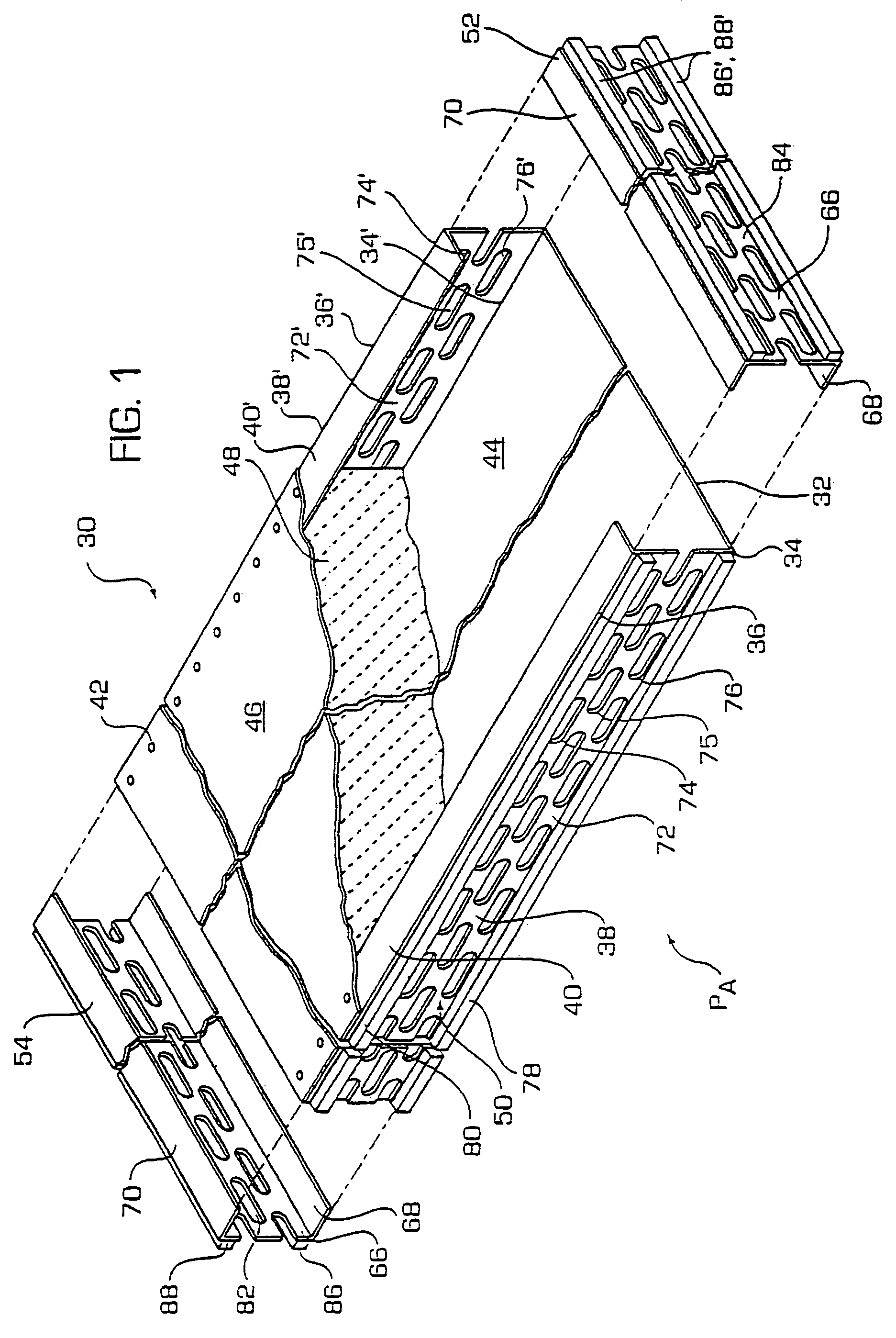
[0041]FIG. 1 provides a partially exploded cut away view of panel assembly 30 of the present invention. As shown in FIG. 1, panel assembly 30 comprises outer shell section 32 which, in a preferred embodiment features a single sheet of panel material that is bent on a first side along a first bend line 34 extending along the long length of the sheet and then along a second parallel bend line 36. The same bend arrangement is provided on the opposite side as represented in FIG. 1 by corresponding bend lines 34′ and 36′

[0042]Between respective bend line pairs 34–36 and 34′–36′ is formed peripheral edge segments 38 and 38′. First support flange section 40 extends inwardly from bend edge 36 and second support flange section 40′ extends inwardly to complete the C-shaped cross-section for outer shell section 32. As shown, peripheral edge segments 38 and 38′ extend transversely off from facing 44 of the outer shell section 32 and flange sections 40, 40′ extend inwardly toward each other and ...


PUM


Abstract

A modular oven, such as a batch process oven, includes a standardized set of self supporting, interconnectable panels which, when assembled, from a self-supporting heat containment shell, free of added structural support members. The present invention is also directed at self-supporting modular oven panels and a method of assembling the panels such as in the expansion or conversion of a first modular oven assembly to a second assembly more conducive to current production requirements.

Description

[0001]The present application is divisional of Ser. No. 10 / 265,475, filed Oct. 7, 2002 now U.S. Pat. No. 6,905,332, which is a continuation of Ser. No. 09 / 645,526, filed Aug. 25, 2000 now abandoned, and which are incorporated herein by reference in their entirety.FIELD OF THE INVENTION[0002]The present invention is directed at a modular oven, such as a batch process oven, comprised of a standardized set of self supporting, interconnectable panels which, when assembled, from a self-supporting heat containment shell, free of added structural support members. The present invention is also directed at self-supporting modular oven panels and a method of assembling the panels such as in the expansion or conversion of a first modular oven assembly to a second assembly more conducive to current production requirements.BACKGROUND OF THE INVENTION[0003]Conventional heat treatment processes, such as a batch oven heat treatment process and other heat treatment process techniques, involve prior ...

Claims


Application Information

Patent Timeline
Patent Type & Authority Patents(United States)
IPC IPC(8): F27D1/00A21B1/00F27B17/00A21B1/24F27B1/00F27B9/02F27D1/16
CPCA21B1/24F27B9/023F27B9/029F27B17/0075F27D1/0006F27D1/0009F27D1/0023F27D1/16
Inventor NEAL, GREGNEAL, DAVID
Owner RAYPAUL INDS
Learn More