Eureka AIR delivers breakthrough ideas for toughest innovation challenges, trusted by R&D personnel around the world.

Method of eliminating residual carbon from flowable oxide fill

a flowable oxide fill and residual carbon technology, applied in the field of semiconductor processing methods, can solve the problems of device degradation, affecting the isolation capability of the trench, etc., and achieve the effect of reducing the level of carbon, easy processing, and easy elimination of carbon

Inactive Publication Date: 2007-04-17
MICRON TECH INC
View PDF44 Cites 63 Cited by
  • Summary
  • Abstract
  • Description
  • Claims
  • Application Information

AI Technical Summary

Benefits of technology

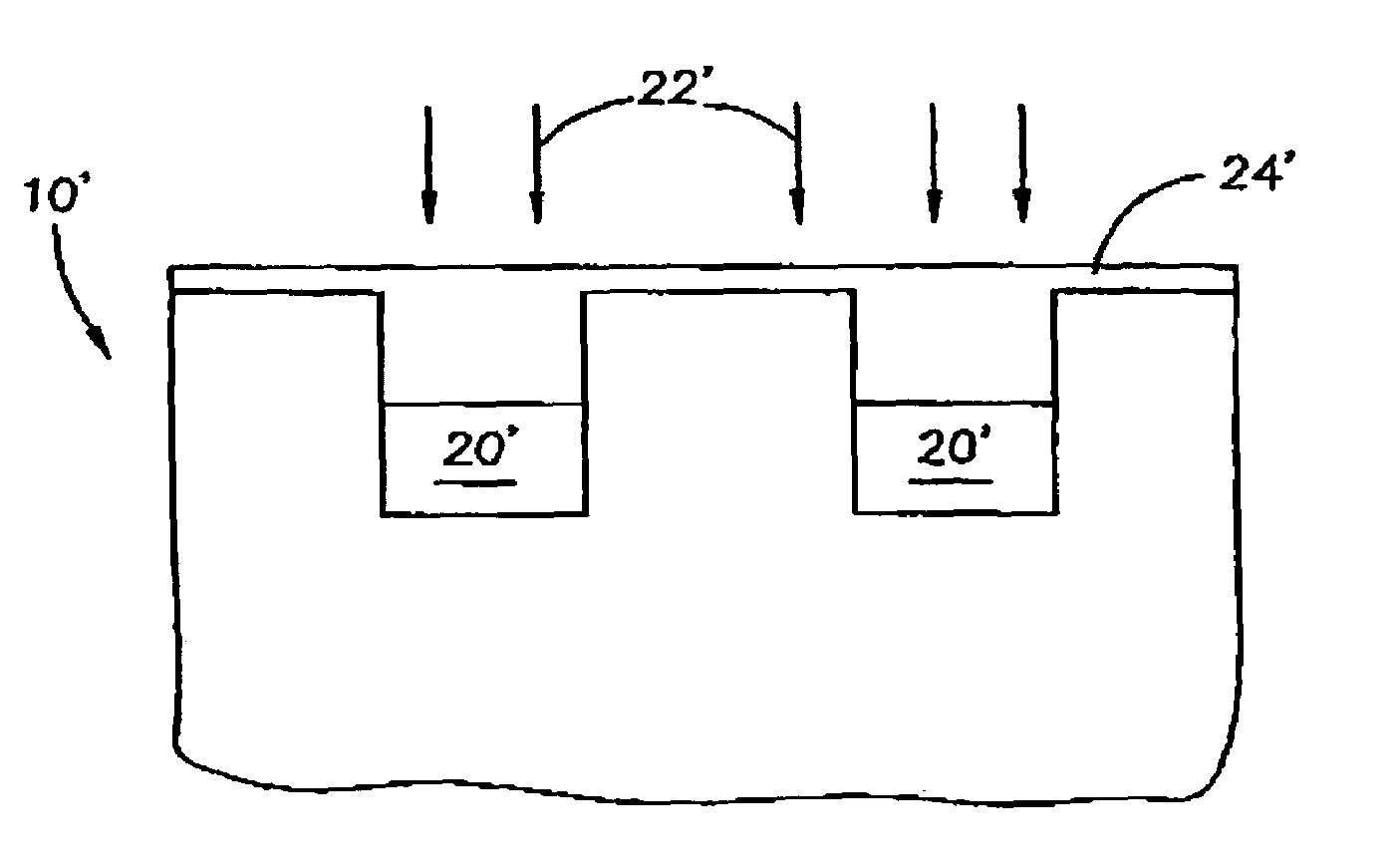
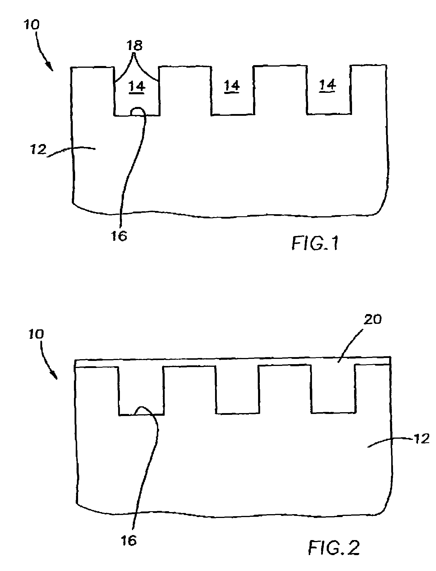
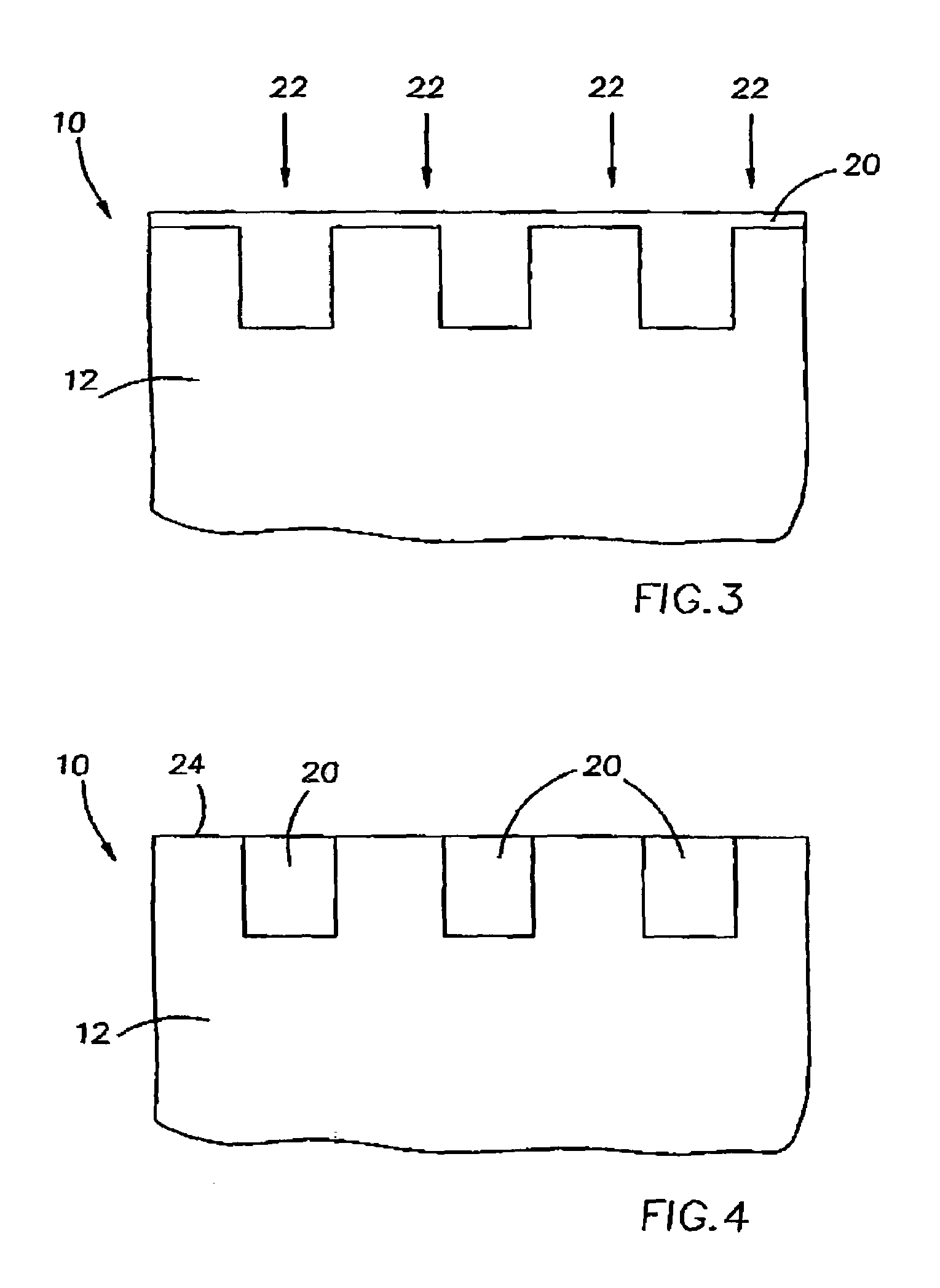
[0011]In yet another embodiment, the method of the invention comprises depositing an oxide material into a high aspect ratio opening such as a deep trench with a flowable oxide material to partially fill the opening (e.g., about one-half of the depth), and then depositing oxide material by high density plasma chemical vapor deposition (HDPCVD) to fill the rest of the opening. This method advantageously eliminates the formation of voids in the fill that can occur when solely a high density plasma oxide is used to fill a high aspect ratio gap.
[0015]The invention advantageously provides a method of readily eliminating carbon from a void-free, flowable oxide material formed in high aspect ratio openings, for example. The post-deposition plasma treatment can be conducted within the same process chamber as the deposition process. The process in accordance with the invention achieves a solid, void-free oxide fill having a reduced level of carbon that can be easily processed and will maintain its integrity in subsequent processing steps.

Problems solved by technology

However, as device dimensions become smaller and trench widths become narrower, such techniques can result in voids formed in the oxide fill, which impair the isolation capability of the trench.
However, the presence of residual carbon from the hydrocarbon portion of the precursor provides a high carbon content in the oxide material that causes the fill to be soft and unstable to various processes such as wet etches, resulting in device degradation.

Method used


Image

  • Method of eliminating residual carbon from flowable oxide fill
  • Method of eliminating residual carbon from flowable oxide fill
  • Method of eliminating residual carbon from flowable oxide fill

Examples


example

[0045]Carbon-containing oxide films were deposited from TMS and O3 by a CVD process onto three wafer surfaces. Process parameters included a chamber pressure of about 100 torr and a wafer temperature of about 125° C., utilizing a Centura DxZ CVD deposition chamber from Applied Materials, Inc.

[0046]The two test films were then treated with an oxygen plasma under the same process parameters. The Control film received no post-deposition treatment with oxygen plasma. Table 1 provides the average of the bulk atomic concentrations (%) of the Test oxide layers and the Control layer.

[0047]

TABLE 1Si bondedSlotCOFto OSi / OTest wafer #1nd63.50.336.10.57(plasma treated)Test wafer #2nd63.30.236.40.58(plasma treated)Control wafer29.836.80.232.60.89

[0048]The results show a significant difference between the average of the bulk atomic concentrations (%) of the oxide layer of the test wafers exposed to the post-deposition treatment and the Control wafer. The results demonstrate that while the untreat...


PUM

PropertyMeasurementUnit
temperatureaaaaaaaaaa
pressureaaaaaaaaaa

Abstract

Methods of forming an oxide layer such as high aspect ratio trench isolations, and treating the oxide substrate to remove carbon, structures formed by the method, and devices and systems incorporating the oxide material are provided.

Description

FIELD OF THE INVENTION[0001]The invention relates generally to semiconductor processing methods of forming and utilizing insulative materials for electrical isolation in integrated circuits, and more particularly to a post-deposition treatment of flowable oxide fill materials to eliminate residual carbon from the material.BACKGROUND OF THE INVENTION[0002]With advancements in semiconductor integrated circuit technology, device dimensions and component spacing continues to shrink, requiring the devices to be placed in close proximity to each other. Insulative materials are widely used in semiconductor fabrication methods for forming structures to electrically isolate the various active components formed in integrated circuits. Devices that extend into a semiconductive substrate can be electrically isolated by insulative materials formed within the substrate between the components, for example, trench isolation regions. In such a technique, trenches are etched into a silicon substrate,...

Claims


Application Information

Patent Timeline
Patent Type & Authority Patents(United States)
IPC IPC(8): H01L21/76H01L21/31C23C16/04C23C16/40C23C16/56H01L21/316H01L21/762
CPCC23C16/045C23C16/401C23C16/56H01L21/02126H01L21/02164H01L21/02211H01L21/02216H01L21/02271H01L21/02282H01L21/0234H01L21/31612H01L21/31633H01L21/76224H01L21/02274
Inventor LI, LILI, WEIMIN
Owner MICRON TECH INC
Why Eureka
Eureka Blog
Learn More