Immersion optical system and optical apparatus having the same
a technology of optical system and optical apparatus, applied in the field of optical system, can solve the problems of na of the optical system not being increased up to na of the optical system not being theoretically increased greater than the refractive index of the glass material,
- Summary
- Abstract
- Description
- Claims
- Application Information
AI Technical Summary
Benefits of technology
Problems solved by technology
Method used
Image
Examples
numerical example
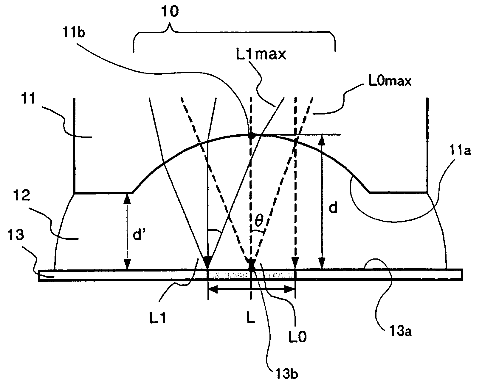
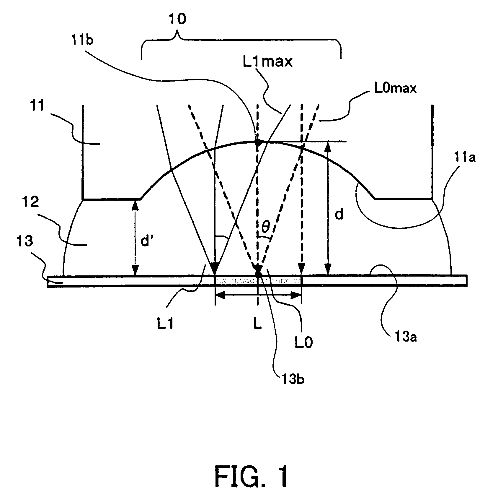
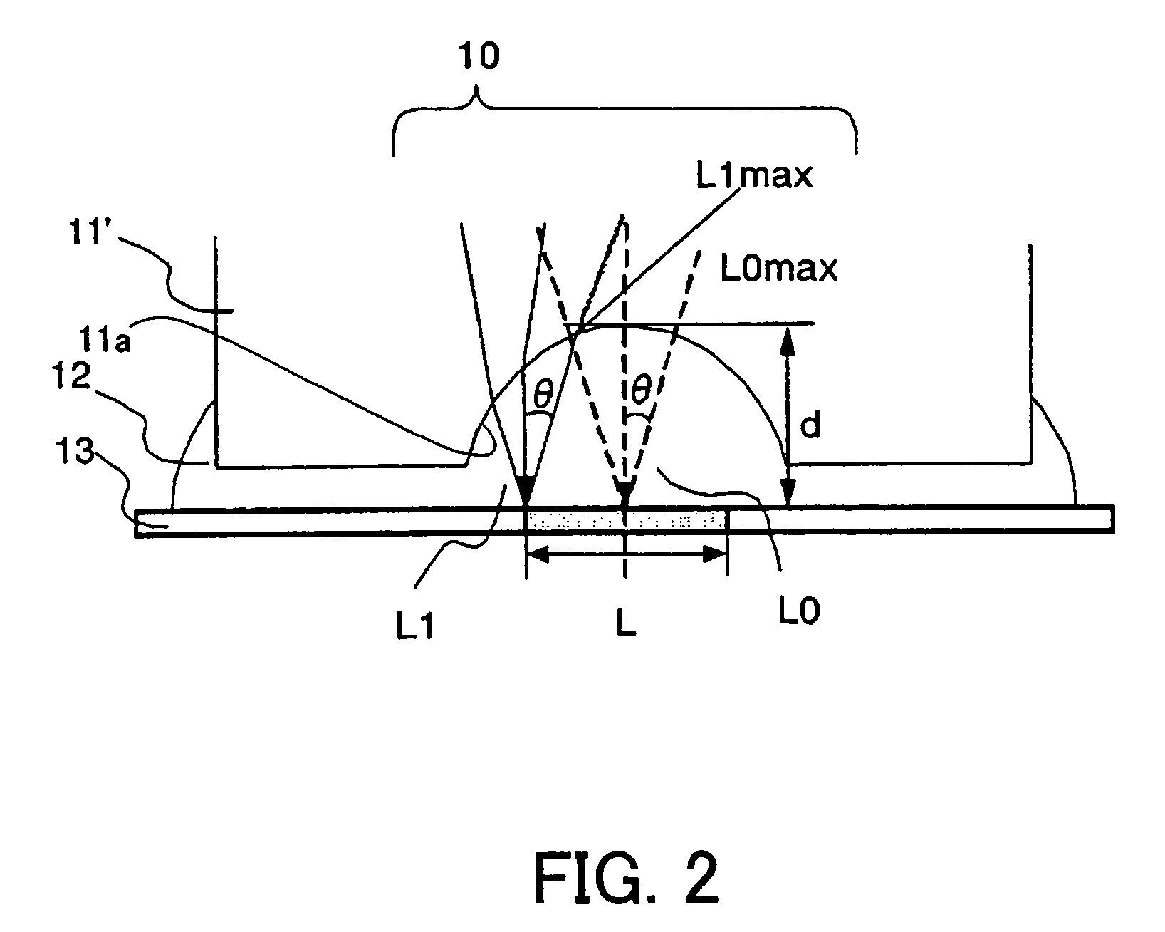
[0109]A numerical example will now be given of the (concave) final lens surface's radius of curvature r and the distance (liquid thickness) d which enable the maximum NA to be greater than the refractive index nl of the glass material, when the refractive index ni of the immersion material is greater than the refractive index nl of the glass material of the final lens.
[0110]FIG. 10 is a view for explaining the light's refraction in the final lens surface when the final lens's glass material has a refractive index of ni, the immersion material has a refractive index of ni (>nl), and the final lens surface has a radius of curvature of r.
[0111]The Snell's law defines the light's refraction at the interface. FIG. 10 shows that a ray 1 from the lens is incident upon a final concave surface at an angle θ1 relative to a surface normal of the final concave surface, is refracted on the final concave surface, is turned to a ray 2 at an angle θ2 relative to the surface normal, and reaches a po...
second embodiment
[0131]While the first embodiment describes the immersion optical system used for a projection optical system in a semiconductor exposure apparatus, the inventive immersion optical system is applicable to another optical system in an optical apparatus, such as an optical disc drive, a laser microscope, which optically records information and reproduces recorded information.
[0132]Referring now to FIG. 17, a description will be given of an immersion optical system used for an objective optical system in a laser microscope 300. In the laser microscope 300, a laser beam 300 emitted from a light source 301 transmits a beam splitter 302 and is scanted by an X-Y scanning optical system 303. The scanned beam 3130 is reflected on a mirror 304, and then irradiated on a target 307 to be observed. An immersion material 306 is filled in a space between a final lens surface 305a and the target 307 in the objective optical system 305, and the beam 310 is emitted and converged from the final lens su...
PUM
 Abstract
Description
Claims
Application Information
 - R&D
- Intellectual Property
- Life Sciences
- Materials
- Tech Scout
- Unparalleled Data Quality
- Higher Quality Content
- 60% Fewer Hallucinations
Browse by: Latest US Patents, China's latest patents, Technical Efficacy Thesaurus, Application Domain, Technology Topic, Popular Technical Reports.
© 2025 PatSnap. All rights reserved.Legal|Privacy policy|Modern Slavery Act Transparency Statement|Sitemap|About US| Contact US: help@patsnap.com


