
Floating bridge amplifier system

Active Publication Date: 2007-03-06
BERRY JOSEPH NORMAN
View PDF6 Cites 4 Cited by
  • Summary
  • Abstract
  • Description
  • Claims
  • Application Information

AI Technical Summary

Benefits of technology

[0014]A floating bridge amplifier system of the present invention includes a pair of DC power supplies, a current gain output section, and a differential voltage gain input section that draws operating current from the DC power supplies through floating DC current regulators. These current regulators effectively isolate the voltage gain section from power supply noise and modulation while creating an operating current loop for the voltage gain section that is independent of ground, allowing for the establishment of positive and negative operating voltages for the voltage gain section. Cross-coupled interstage loading provides a low-noise bootstrap that enables nearly rail-to-rail output voltage swing while forming a local corrective feedback loop around the output section. This local feedback yields improved distortion and load control without the need for a class A output stage or high global negative feedback. In addition, the floating operation of the current regulators improves their performance by minimizing voltage fluctuations across them which can modulate their output currents.

Problems solved by technology

It is known in the art that heavy use of global negative feedback can lead to poor transient response, marginal stability, and increased high-order residual distortion products, all of which can degrade perceived amplifier sound quality.
Significant drawbacks and limitations of previous embodiments include:a) The need for both floating and fixed polarity DC power supplies.
Power transformers typically are among the most costly components in an amplifier, so either of these solutions adds significant cost, and may also complicate power supply wiring and fusing.b) The need for a Class A output stage.
This mandates more rigorous and expensive thermal management for the output section, and necessitates the use of heavy-duty power supply components to avoid excessive voltage sag, heating, and noise.
These requirements contribute to a design that is more complex and costly to build, and more expensive and inconvenient to operate due to its increased bulk, power consumption, and waste heat.c) The requirement to isolate the voltage gain section from power supply noise and modulation in order to maintain high linearity and low noise.
The decoupling networks offer effective noise isolation at the cost of reduced operating voltage, potentially limiting the maximum output signal swing.
The problem of limited signal swing is overcome by adding resistive bootstrap circuits, but these circuits couple power supply noise and modulation into the signal path, and thus work against the goal of high open-loop performance.
Thus, it is apparent that the use of floating bridge amplifier systems in audio, while highly desirable, still entails significant limitations and drawbacks.

Method used


Image

  • Floating bridge amplifier system
  • Floating bridge amplifier system
  • Floating bridge amplifier system

Examples


Embodiment Construction

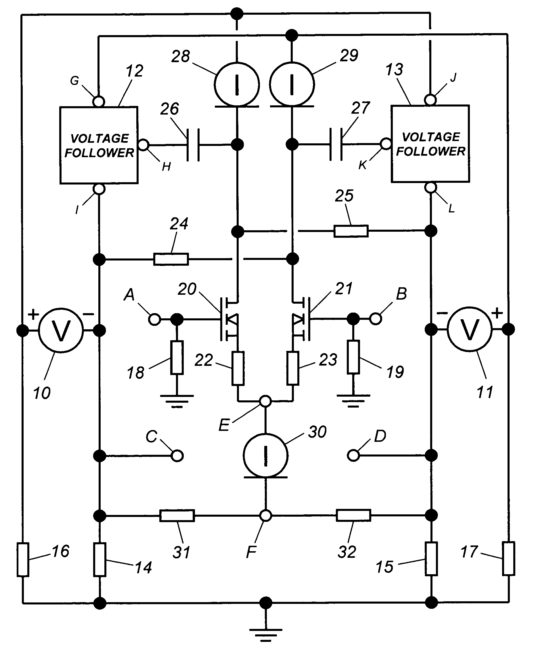
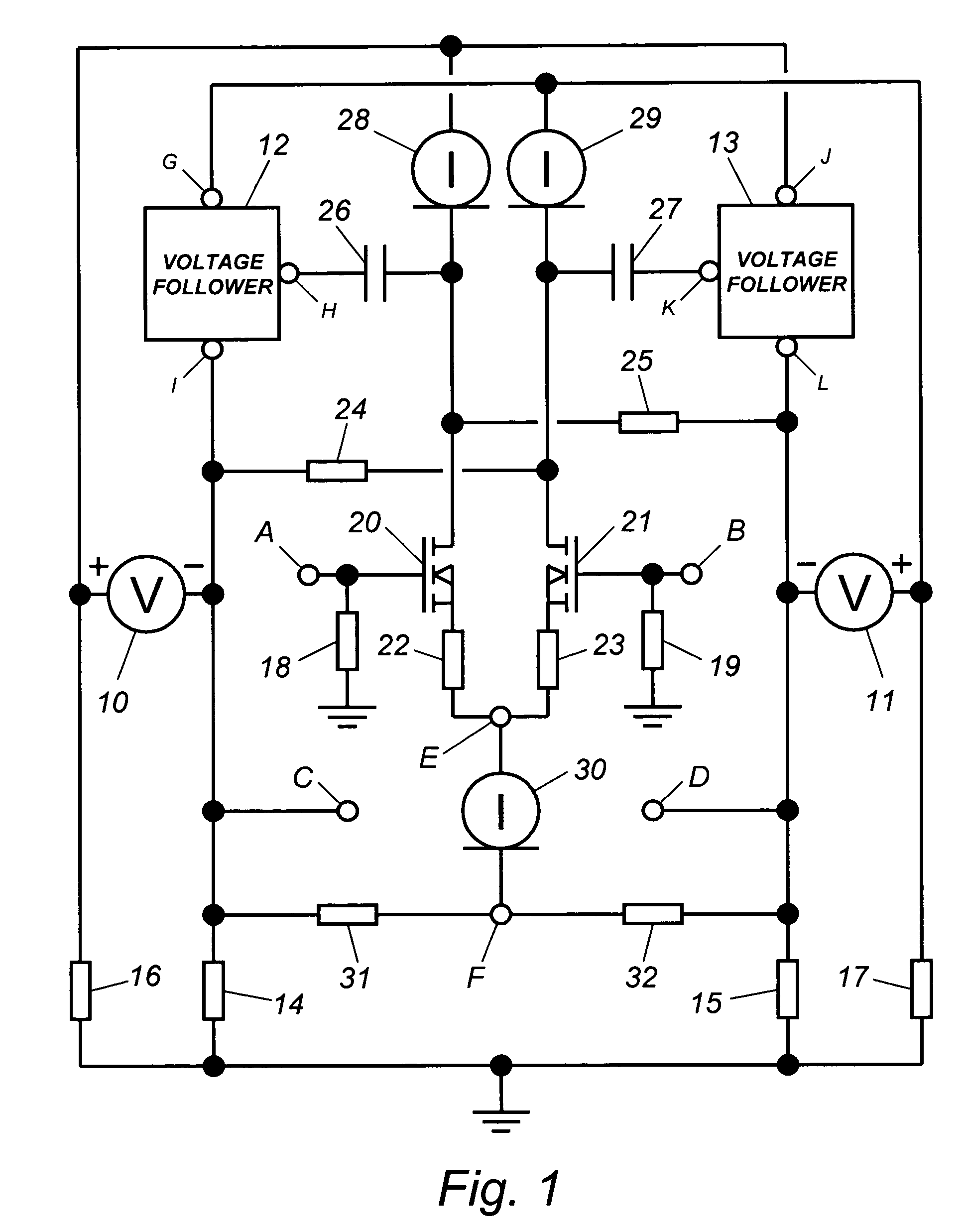
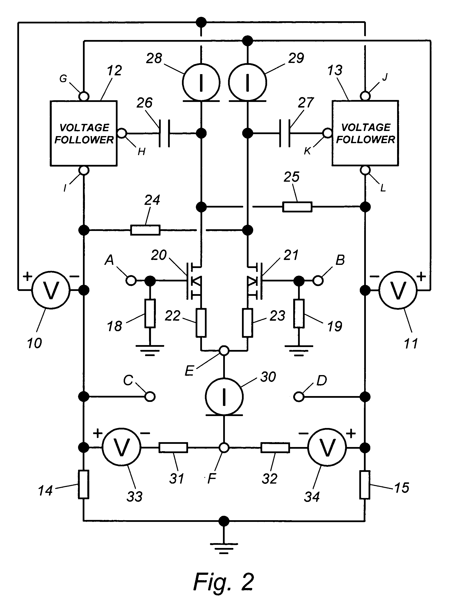
[0017]The schematic of FIG. 1 shows a preferred embodiment of the amplifier system. Operating voltage and current are provided by floating DC power supplies 10,11 and ground-referenced voltage divider networks 14,16 and 15,17. The output current gain section is represented by voltage followers 12,13, each having an input or control terminal H,K, a supply terminal G,J and an output terminal I,L, and being of suitable internal construction to maintain control of the voltage across a load connected at amplifier output terminals C,D. The voltage gain section includes amplifier input terminals A,B, input impedances 18,19, voltage gain devices 20,21, gain impedances 22,23, interstage load impedances 24,25, interstage coupling means 26,27, floating supply current regulators 28,29, floating bias current regulator 30, and current impedances 31,32.

[0018]DC power supplies 10,11 may be any sources of reasonably stable DC power capable of providing the required voltage and current for the applic...


PUM


Abstract

An audio amplifier system includes at least a pair of DC power supplies, a floating bridge current gain output section, and a differential voltage gain input section that draws operating current from the DC power supplies through floating DC current regulators. The included current regulators reject power supply noise and modulation and provide a floating current path for establishing positive and negative operating voltages for the voltage gain section. Cross-coupled interstage loading enables nearly rail-to-rail output voltage swing while providing local feedback around the output section for reduced distortion and improved output load control. The floating current regulators in the circuit exhibit enhanced performance as a result of suppressed operating voltage fluctuations.

Description

CROSS-REFERENCE TO RELATED APPLICATIONS[0001]This application is entitled to the benefit of Provisional Application Ser. No. 60 / 538,029 filed Jan. 21, 2004.BACKGROUND OF THE INVENTION[0002]This invention relates to amplifiers, and more specifically, to a high fidelity audio amplifier or preamplifier system incorporating a floating bridge circuit topology.[0003]A floating bridge or “circlotron” amplifier includes a floating bridge output section in which a pair of voltage follower devices or circuits and a pair of floating DC power supplies are arranged as a balanced bridge. Practical amplifier systems of this type also generally include a preceding voltage gain section to raise an applied input signal voltage to the required output level and to supply a differential drive signal to the output section. Ideally, the included voltage gain section provides linear gain over a wide range, has ground-referenced input terminals to allow for direct coupling of a signal source, and is simple ...

Claims


Application Information

Patent Timeline
IPC IPC(8): H03F3/00H03F3/217
CPCH03F3/68H03F3/20
Inventor BERRY, JOSEPH NORMAN
Owner BERRY JOSEPH NORMAN
Learn More