
Method for manufacturing thin-film multilayer electronic component and thin-film multilayer electronic component

a multi-layer electronic component and multi-layer technology, applied in the direction of fixed capacitors, stacked capacitors, fixed capacitor details, etc., can solve the problems of difficult to reduce the size of monolithic ceramic capacitors and increase the capacitance, and achieve the effect of efficient and economical production

Inactive Publication Date: 2007-02-20
MURATA MFG CO LTD
View PDF21 Cites 2 Cited by
  • Summary
  • Abstract
  • Description
  • Claims
  • Application Information

AI Technical Summary

Benefits of technology

[0017]In order to overcome the problems described above, preferred embodiments of the present invention provide a method for efficiently and economically manufacturing a miniaturized, high-performance thin-film multilayer electronic component, and a thin-film multilayer electronic component manufactured by the method.

Problems solved by technology

Thus, it is impossible to form a thin dielectric layer having a thickness smaller than the particle size of the ceramic powder material.
This makes it difficult to reduce the size of the monolithic ceramic capacitor and increase the capacitance.
In the case of manufacturing an ultra-miniature chip capacitor, unfortunately, it is difficult to handle chips, into which a wafer is cut, to form the external electrodes, and this negatively affects production efficiency.
The above-described problems hold true for other thin-film multilayer electronic components without being limited to the thin-film multilayer capacitors.

Method used


Image

  • Method for manufacturing thin-film multilayer electronic component and thin-film multilayer electronic component
  • Method for manufacturing thin-film multilayer electronic component and thin-film multilayer electronic component
  • Method for manufacturing thin-film multilayer electronic component and thin-film multilayer electronic component

Examples


Embodiment Construction

[0042]The present invention will further be illustrated in detail with reference to preferred embodiments thereof.

[0043]Preferred embodiments will be described using a thin-film multilayer capacitor as the thin-film multilayer electronic component.

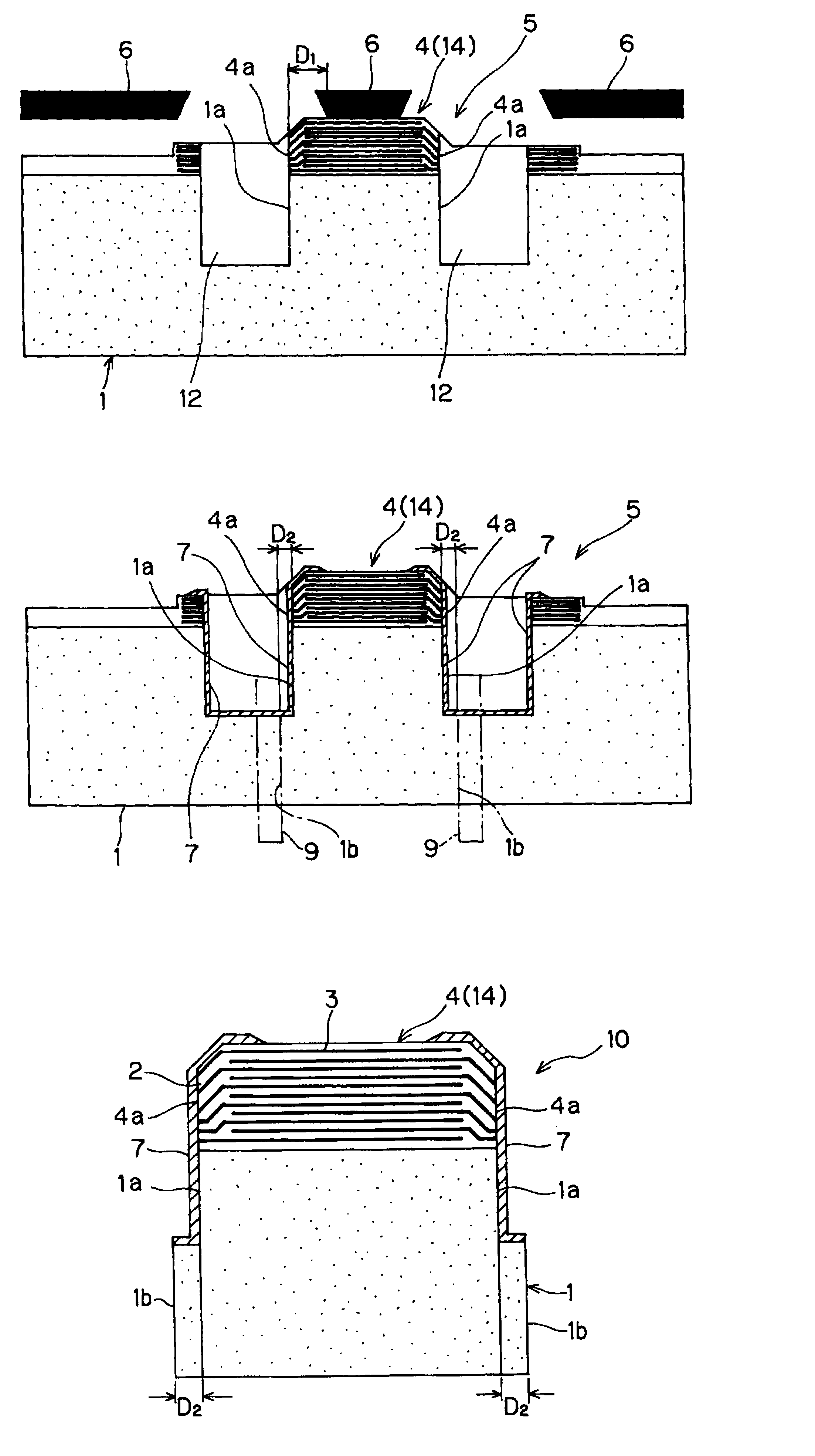
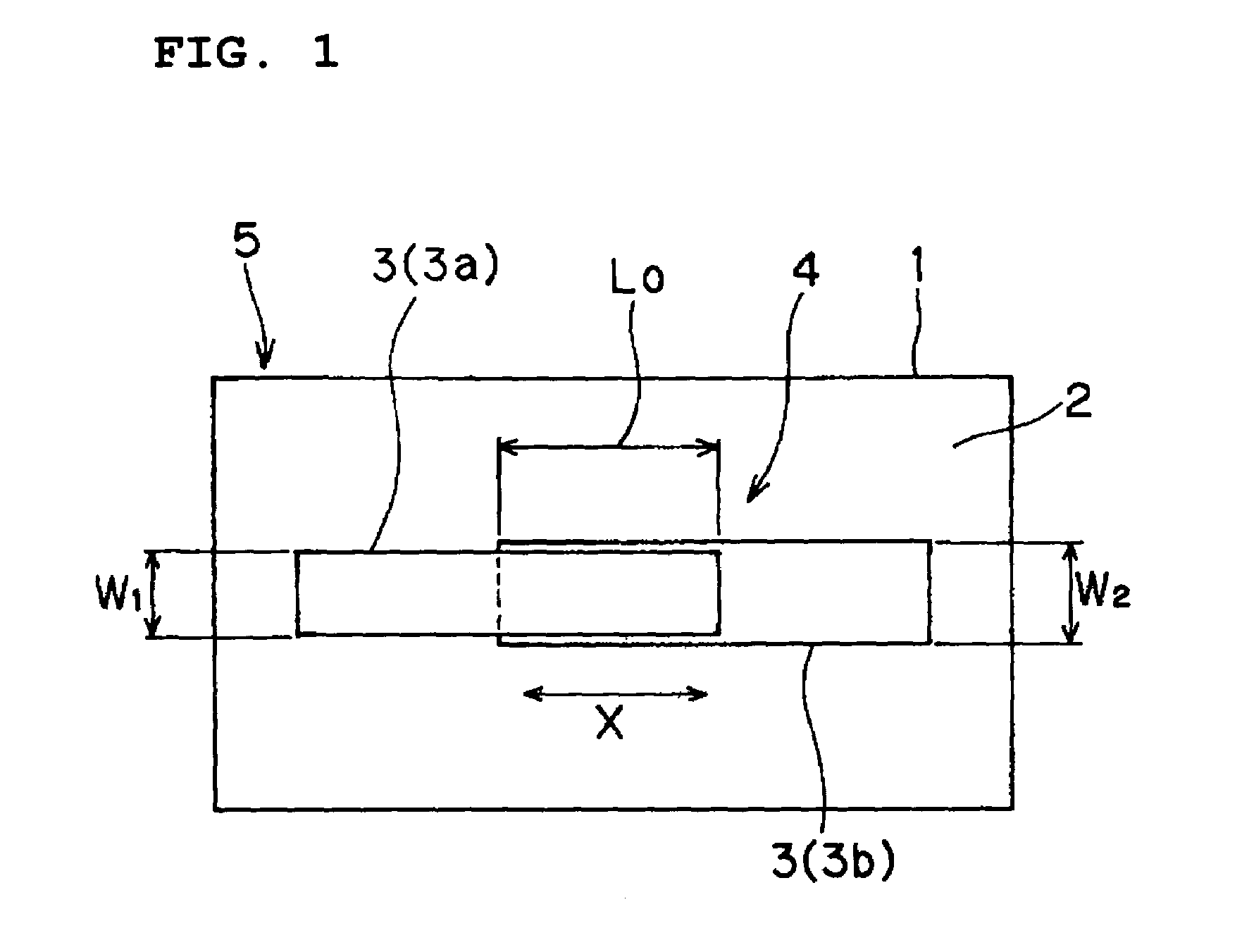
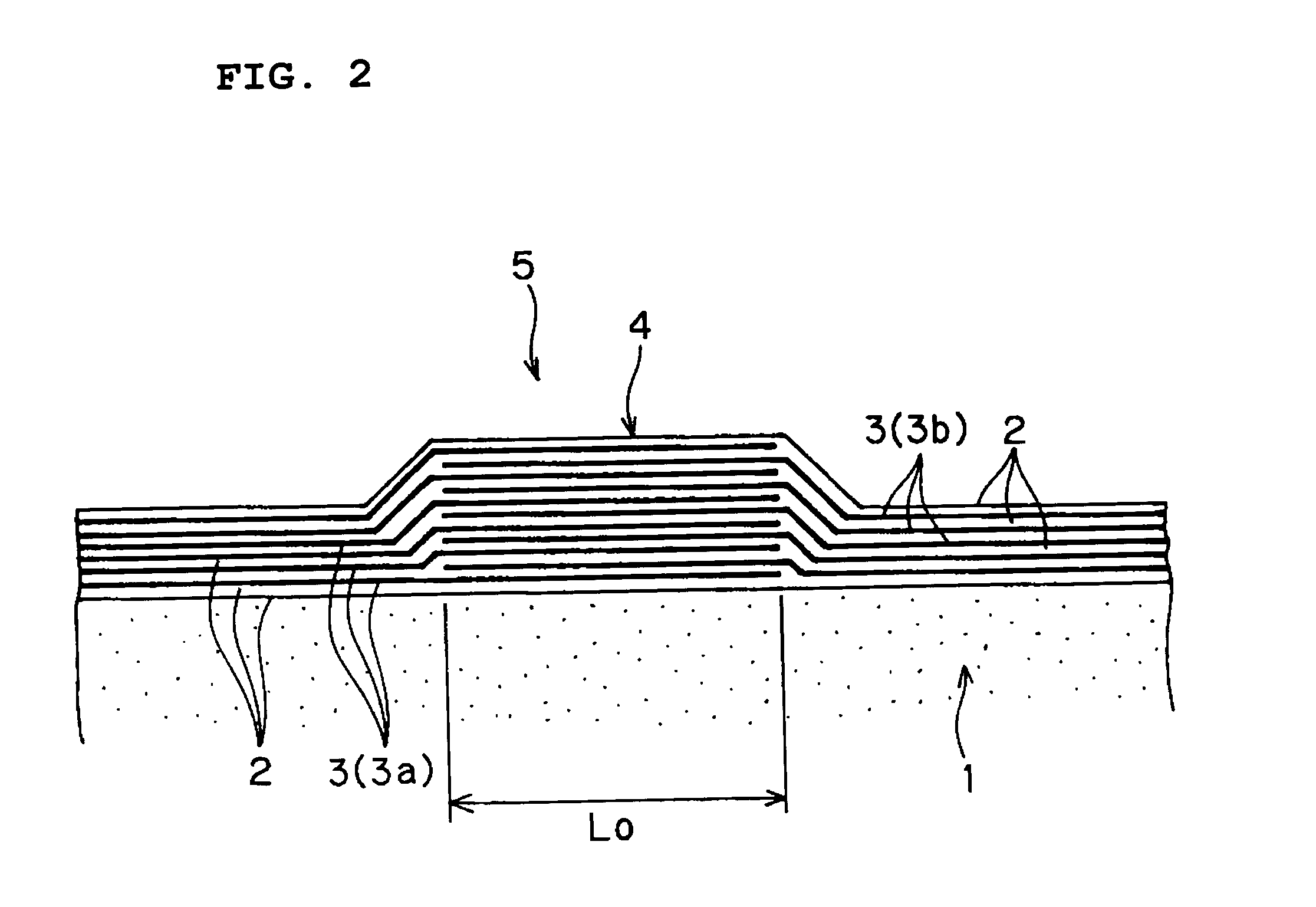
[0044]FIG. 1 is a transparent plan view of a laminate according to a preferred embodiment, prepared by layering dielectric thin films and thin-film internal electrodes on a substrate; FIG. 2 is a front sectional view of main portions of the laminate; FIG. 3 is a plan view of a laminated structure including the substrate and the laminate, having grooves; and FIG. 4 is a front sectional view of the structure shown in FIG. 3.

[0045](1) Dielectric thin films 2 and thin-film internal electrodes 3 are alternately deposited on a sapphire substrate 1 having a thickness of about 0.2 mm, as shown in FIG. 1, to prepare a laminate 4 (see FIG. 2). In this instance, the thin-film internal electrodes 3 are alternately displaced in a predetermined directio...


PUM

PropertyMeasurementUnit
thicknessaaaaaaaaaa
thicknessaaaaaaaaaa
thicknessaaaaaaaaaa

Abstract

In a method for manufacturing a thin-film multilayer electronic component, dielectric thin films and thin-film internal electrodes are alternately layered on each other to form a laminate. The thin-film internal electrodes are alternately displaced in a predetermined direction to form an overlap portion. The entire thickness of the laminate and a portion of the thickness of the substrate are cut to form grooves in portions other than the overlap portion, in a direction that is substantially perpendicular to the predetermined direction. External electrodes are formed on at least the cut surfaces of the laminate and the half-cut surfaces of the substrate. Then, the substrate is fully cut in the thickness direction along the grooves such as not to substantially remove the external electrodes.

Description

BACKGROUND OF THE INVENTION[0001]1. Field of the Invention[0002]The present invention relates to multilayer electronic components, and more particularly, to a method for manufacturing a miniaturized thin-film multilayer electronic component, such as a thin-film multilayer capacitor, having a relatively high capacitance and further relates to such a thin-film multilayer electronic component.[0003]2. Description of the Related Art[0004]A monolithic ceramic capacitor, which is typical of multilayer electronic components, is generally manufactured through the following steps:[0005](1) An electrode paste is printed on ceramic green sheets having a predetermined size.[0006](2) Then, a predetermined number of the ceramic green sheets are layered on one another, and ceramic green sheets not printed with the electrode paste are further layered on the upper and lower surfaces of the layered ceramic sheets, followed by contact-bonding under predetermined conditions to prepare a laminate.[0007]...

Claims


Application Information

Patent Timeline
Patent Type & Authority Patents(United States)
IPC IPC(8): H01L29/00H01G4/33H01G4/12H01G4/232H01G4/30H01L21/02
CPCH01G4/1218H01G4/30H01G4/232
Inventor TAKESHIMA, YUTAKA
Owner MURATA MFG CO LTD
Learn More