
Non-newtonian flow fluid-locking mechanism for vehicles

a technology of fluid-locking mechanism and vehicle, which is applied in the direction of mechanical equipment, shock absorbers, transportation and packaging, etc., can solve the problems of high cost and present a hazard to the operator, and achieve the effects of reducing manufacturing times and costs, reducing the risk of injury, and reducing costs

Inactive Publication Date: 2007-01-23
DOUGLAS AUTOTECH
View PDF19 Cites 37 Cited by
  • Summary
  • Abstract
  • Description
  • Claims
  • Application Information

AI Technical Summary

Benefits of technology

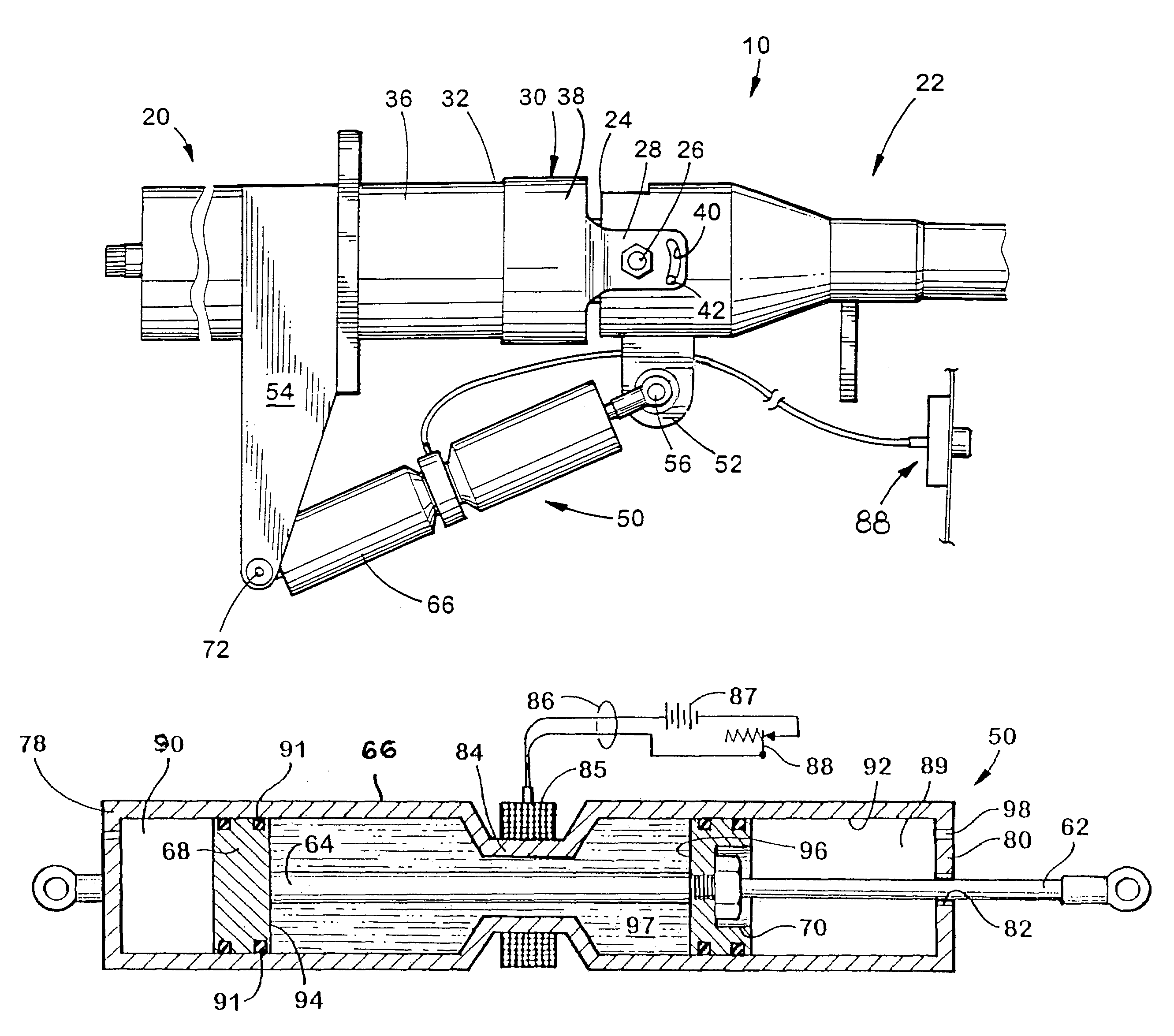
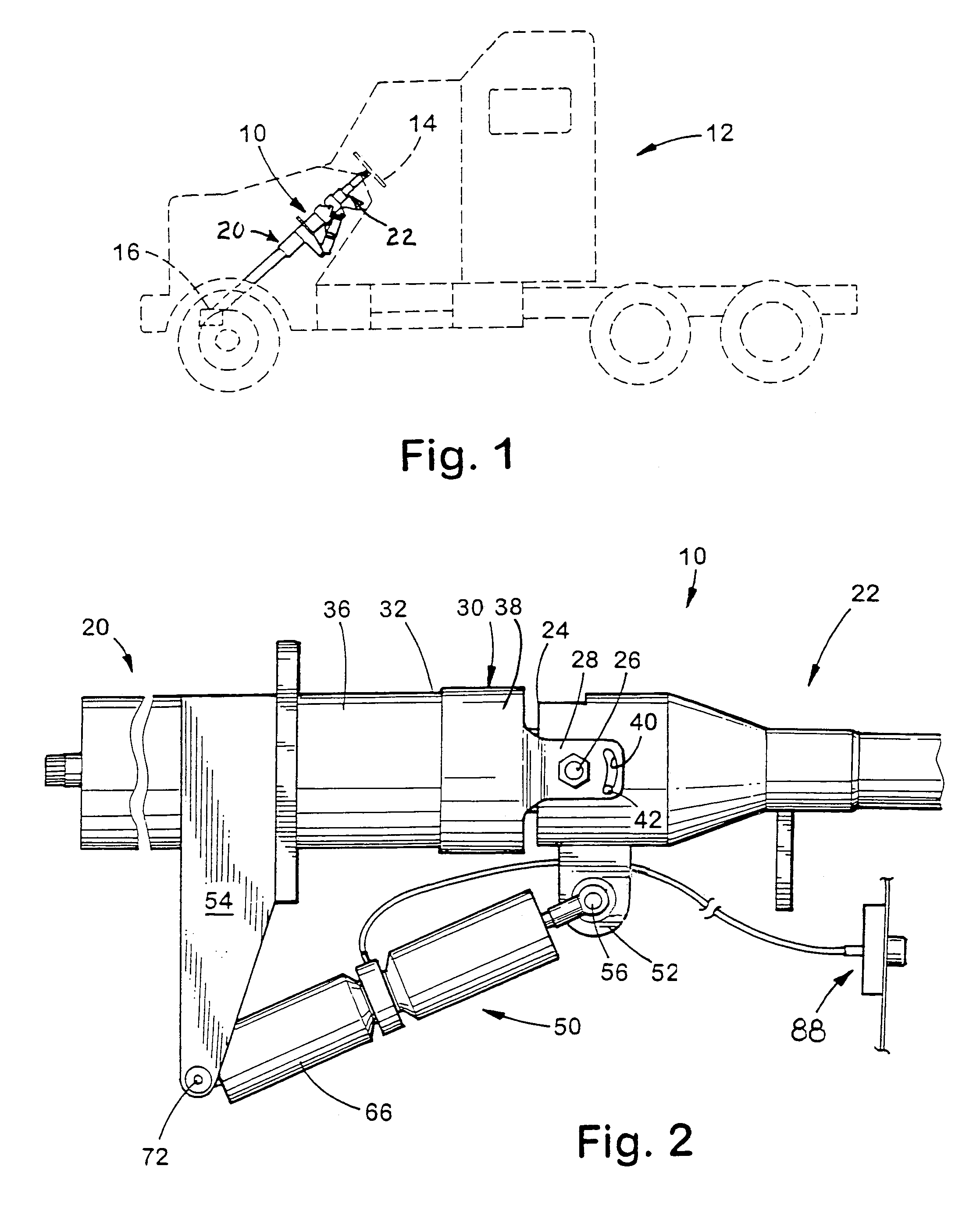
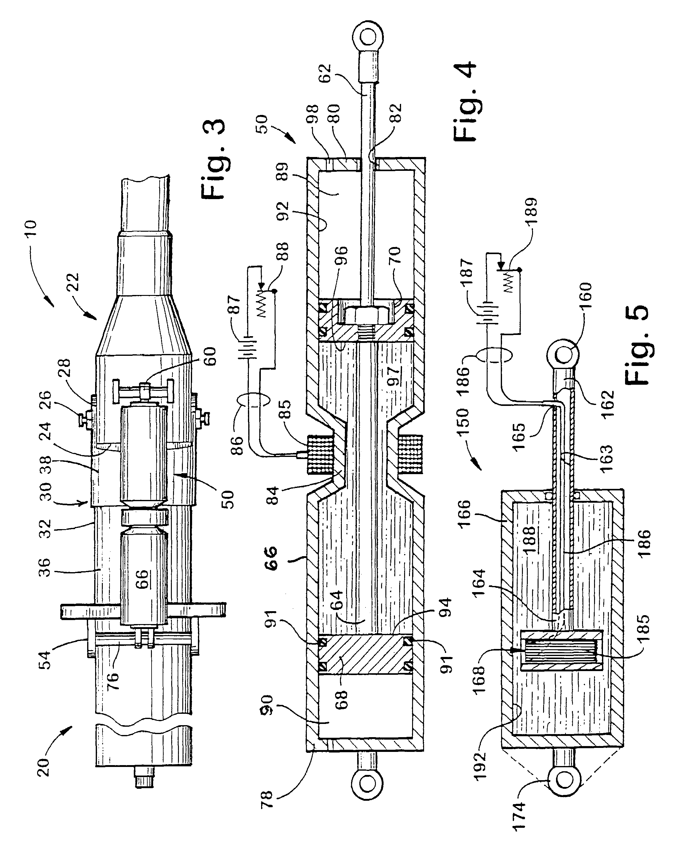
[0010]The advantages provided by the instant invention include a method and apparatus for selectively fixing the relative position of one object to another. Examples include changing the tilt angle and / or longitudinal position of a steering wheel with respect to the steering column. The compact nature of the instant invention reduces manufacturing times and costs associated with assembly because complex stampings, pawls, and slots are eliminated, resulting in fewer parts than conventional adjustable steering column assemblies, translating into lower cost. Additionally, the mechanism easily interfaces with other safety mechanisms to permit repositioning of the vehicle control components in the event of a crash to reduce the risk of injury to the operator. The mechanism may be adjusted to absorb some of the impact by the operator to reduce injury, or rapidly fall away from the operator to reduce the risk of contact entirely. It is contemplated that pre-positioning devices such as pyrotechnic actuators may be used in combination with this invention to reposition vehicle components such as the steering wheel and column in the event of an accident.

Problems solved by technology

However, the mechanisms used to provide the adjustment over a limited range of positions; were subject to mechanical failure or wear, and were expensive to manufacture resulting in higher costs.
Furthermore, once the particular control or object was in position, it remained fixed in an accident and presented a hazard to the operator.

Method used


Image

  • Non-newtonian flow fluid-locking mechanism for vehicles
  • Non-newtonian flow fluid-locking mechanism for vehicles
  • Non-newtonian flow fluid-locking mechanism for vehicles

Examples


Embodiment Construction

[0025]For purposed of the following description, the terms “upper”, “lower”, “right”, “left”, “rear”, “front”, “vertical”, “horizontal” and derivatives thereof shall relate to the invention as oriented in FIG. 2. However, it is to be understood that the invention may assume various alternative orientations except where expressly specified to the contrary. It is also to be understood that the specific devices and processes illustrated in the attached drawings, and described in the following specification, are simply exemplary embodiments of the inventive concepts defined in the specification and any appended claims. Specific dimensions and other physical characteristics relating to the embodiments disclosed herein are not to be considered as limiting, unless the claims expressly state otherwise.

[0026]The instant invention has application to substantially any situation where it is desired to adjustably position one component relative to another. For the sake of simplicity, the followi...


PUM


Abstract

An assembly is provided for fixing the position of an adjustable component (22) of a vehicle, comprising in combination a fixed reference frame (20) within the vehicle such as a dash or a firewall, an adjustable component (22) also disposed in the vehicle such as an adjustable steering column (10), pedals, or a seat. Interconnecting the fixed reference frame (20) and the adjustable component (22) is a fluid locking mechanism (50) which permits selective positioning of the adjustable component relative to the fixed reference frame (20) and holds the adjustable component (22) in position. The fluid locking mechanism (50) is preferably a non-Newtonian flow fluid locking mechanism which uses a magneto-rheological fluid (97) to fix the position of the adjustable component (22) in place once the desired position is selected. To provide additional safety for the vehicle occupants, the fluid locking mechanism may be controlled by an electrical microprocessor (556) or circuit which adjusts the locking strength of the fluid locking mechanism (50) based upon user inputs and dynamic events.

Description

CROSS REFERENCE TO RELATED APPLICATIONS[0001]This application claims priority from and is a continuation of PCT application serial number PCT / US99 / 30431, filed Dec. 20, 1999, which claims priority from U.S. provisional patent application Ser. Nos. 60 / 113,084 filed Dec. 21, 1998, and 60 / 164,438, filed Nov. 9, 1999, the contents of which are incorporated herein by reference.BACKGROUND OF THE INVENTION[0002]1. Field of the Invention[0003]This invention relates generally to devices for adjusting the position of one object relative to another and more particularly to a fluid-locking mechanism for fixing the position of one object relative to another, such as automobile seats, control pedals, the tilt and telescope position of a steering column, and the like.[0004]2. Discussion of the Related Art[0005]Traditionally, adjustable components in a vehicle have been temporarily fixed in position using mechanical locking systems. Such systems included some pawl, detent, or similar structure enga...

Claims


Application Information

Patent Timeline
IPC IPC(8): B60D1/18
CPCB62D1/184F16F9/56F16F9/535B62D1/195
Inventor SHA, SUBINSPENCER, JOSEPHBOWERMAN, BRIAN
Owner DOUGLAS AUTOTECH
Learn More