
Cervical isolation and delivery apparatus

a cervical isolation and delivery device technology, applied in the field of medical instruments, can solve the problems of irritation of the vagina or outer vulva, leakage onto the vulva, and extreme pain for the patient, and achieve the effects of less resistance, less irritation, and easy patient isolation

Inactive Publication Date: 2007-01-23
WEST VIRGINIA UNIVERSITY
View PDF17 Cites 31 Cited by
  • Summary
  • Abstract
  • Description
  • Claims
  • Application Information

AI Technical Summary

Benefits of technology

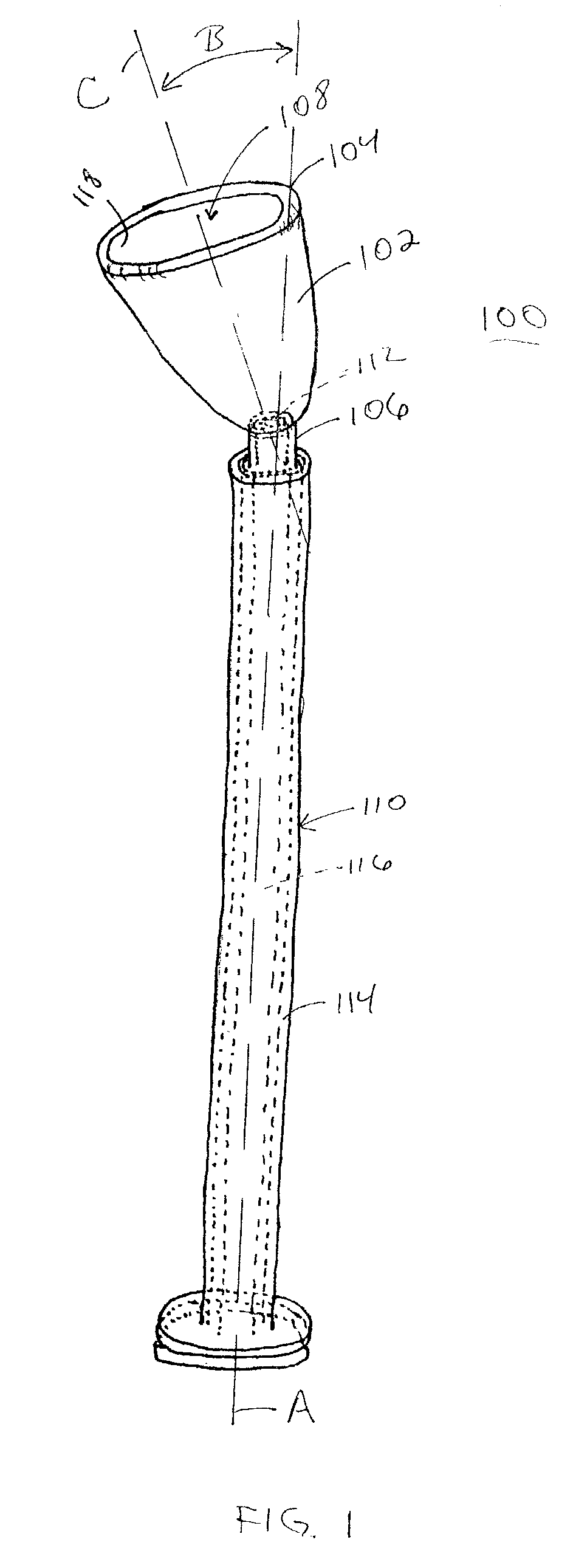
[0024]An advantage of the invention is that the cervical cap is angled and is available in multiple sizes, thereby making it easier for the user to isolate the patient's cervix and to custom fit the cervical cap for a specific patient.
[0025]Another advantage of the invention is that the lip around the open end of the cervical cap eliminates sharp edges and provides a seal around the patient's cervix.
[0026]Another advantage of the invention is that little or no therapeutic agent accumulates in the transition area between the elongated hollow tube and the cervical cap because the smooth interior surface of the base of the cervical cap extends down into the neck of the hollow elongated tube.
[0027]Another advantage of the invention is that the second expelling surface delivers the one or more cervical agents directly into the cervical cap because the second expelling surface sits flush, or almost flush, with the bottom of the cervical cap.
[0028]Another advantage of the invention is that the elongated rod passes through the internal chamber of the elongated hollow tube with little resistance until just prior to expelling the one or more cervical agents from the elongated hollow tube.
[0029]Another advantage of the invention is a plurality of ridge or grooves on the interior surface of the elongated hollow tube for regulating the flow of a therapeutic agent.

Problems solved by technology

Currently, therapeutic agents, e.g. misoprostol, are delivered to a human cervix either by inserting a tablet or gel directly into a patient's vagina, which exposes both the vagina and cervix to the agent, or by direct injection of the agent into the cervix with a needle, which can be extremely painful to the patient.
The disadvantage with these procedures, however, is that several agents designed for drug therapy to the cervix are either systemically toxic or cause irritation to the vagina or outer vulva.
The disadvantage with creams is that they often leak out onto the vulva and become extremely irritating and painful.
Currently, there are no other established methods for administering anesthetic agents to a patient's cervix other than direct injection of the anesthetic via a needle and syringe.
Most patient's report this injection to be more painful and uncomfortable than the procedure (which itself is uncomfortable and sometimes painful).
There are many disadvantages with using Misoprostol for this off-label use.
First, this topical use is directly counter to the drug's allowed use.
Second, the tablet form of Misoprostol is intended for oral ingestion only—not as a topical agent.
In addition the tablet may be difficult to position properly so as to directly contact the cervix.
Lastly and most importantly, the proper dosage of Misoprostol has not been ascertained or even studied because this use of Misoprostol is a non-labeled use.
This device is not designed to fit closely around the cervix.
While the various devices and methods are aimed either at isolating or treating a patient's cervix, none provides an effective means to both deliver a medicine to the patient's cervix while simultaneously isolating the cervix from surrounding anatomical structures.

Method used


Image

  • Cervical isolation and delivery apparatus
  • Cervical isolation and delivery apparatus
  • Cervical isolation and delivery apparatus

Examples


Embodiment Construction

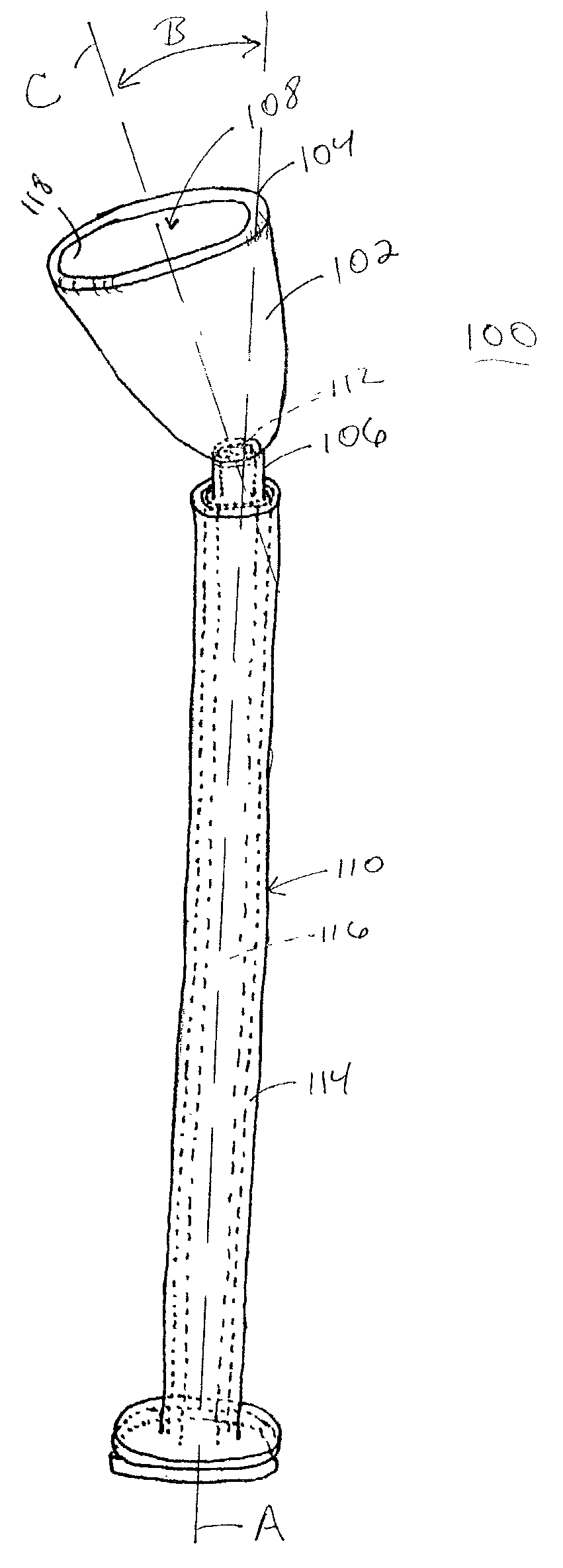
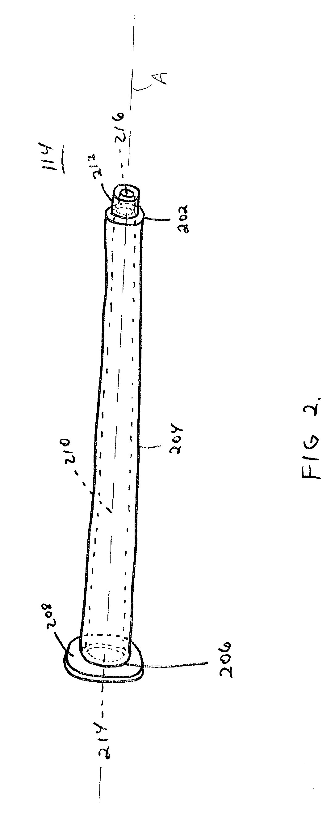
[0037]The present invention uses a cervical isolation device (CID) 100 to isolate and treat a patient's cervix. Nonlimiting examples of cervical treatments include delivering one or more therapeutic agents to the cervix, performing a biopsy or other surgery, or collecting cervical cells for analytical testing, e.g., PAP smears. Therapeutic agents include, without limitation, anesthetics, anti-virals, anti-neoplastics, and cervical ripening agents, e.g., Misoprostol. The CID 100 preferably includes a cervical cap 102 removably connected to an end of a syringe 110.

Cervical Cap:

[0038]The cervical cap 102 preferably is shaped e.g., bell-shaped, such that upon insertion of the CID 100 in a patient's vagina, the cervical cap 102 surrounds and covers the patient's cervix thereby isolating the cervix from the surrounding tissues. See FIGS. 1 and 4. Once isolated, the cervix is treated without affecting surrounding tissue. To this end, the cervical cap 102 has a front opening 108 that is wid...


PUM


Abstract

A cervical isolation and delivery apparatus having a cervical cap removably connected to a syringe such that a bottom opening of the cervical cap is in communication with an internal chamber of the syringe. The syringe is an elongated hollow tube with an elongated rod slidable disposed within an internal chamber of the elongated hollow tube. The cervical cap is removably connected to an application end of the elongated hollow tube such that upon insertion of the apparatus into a patient's vagina, the cervical cap covers the patient's cervix while protecting the tissue surrounding the cervix. The patient's cervix is treated by placing medication, e.g., one or more therapeutic agents, in the elongated hollow tube such that the elongated rod is in an extended position, inserting the apparatus into a patient's vagina, positioning the cervical cap over the patient's cervix, and pushing the elongated rod through the internal chamber of the elongated hollow tube until it is in a retracted position, thereby expelling the medication from the internal chamber into and through the cervical cap and into contact with the patient's cervix. The cervical cap covers and isolates the cervix thereby preventing the medication from leaking from the cervical area and irritating surrounding tissue.

Description

RELATED APPLICATIONS[0001]This application is a continuation-in-part of U.S. patent application Ser. No. 09 / 649,170, filed Aug. 25, 2000 now U.S. Pat. No. 6,526,980, that claims the benefit of U.S. patent application 60 / 150,785, filed Aug. 26, 1999.BACKGROUND OF THE INVENTION[0002]1. Field of the Invention[0003]This invention relates to medical instruments, and more specifically, to a medical instrument for isolating a patient's cervix.[0004]2. Related Art[0005]Currently, therapeutic agents, e.g. misoprostol, are delivered to a human cervix either by inserting a tablet or gel directly into a patient's vagina, which exposes both the vagina and cervix to the agent, or by direct injection of the agent into the cervix with a needle, which can be extremely painful to the patient. The disadvantage with these procedures, however, is that several agents designed for drug therapy to the cervix are either systemically toxic or cause irritation to the vagina or outer vulva. Alternatively, othe...

Claims


Application Information

Patent Timeline
IPC IPC(8): A61F6/06A61F6/08A61F6/12A61F13/26
CPCA61F6/08A61F13/26A61F6/12
Inventor TRACY, TIMOTHY S.GLOVER, DOUGLAS D.CALLERY, PATRICK S.SOISSON, ANDREW P.SMITH, JAMES E.
Owner WEST VIRGINIA UNIVERSITY
Learn More