
Method and apparatus for downhole fluid characterization using flexural mechanical resonators

a flexural mechanical and resonator technology, applied in the field of downhole fluid analysis, can solve the problem of no method or apparatus for measuring viscosity in the downhole environment, and achieve the effect of reducing the effect of abrasion and preventing contact corrosion

Inactive Publication Date: 2007-01-16
BAKER HUGHES INC
View PDF60 Cites 26 Cited by
  • Summary
  • Abstract
  • Description
  • Claims
  • Application Information

AI Technical Summary

Benefits of technology

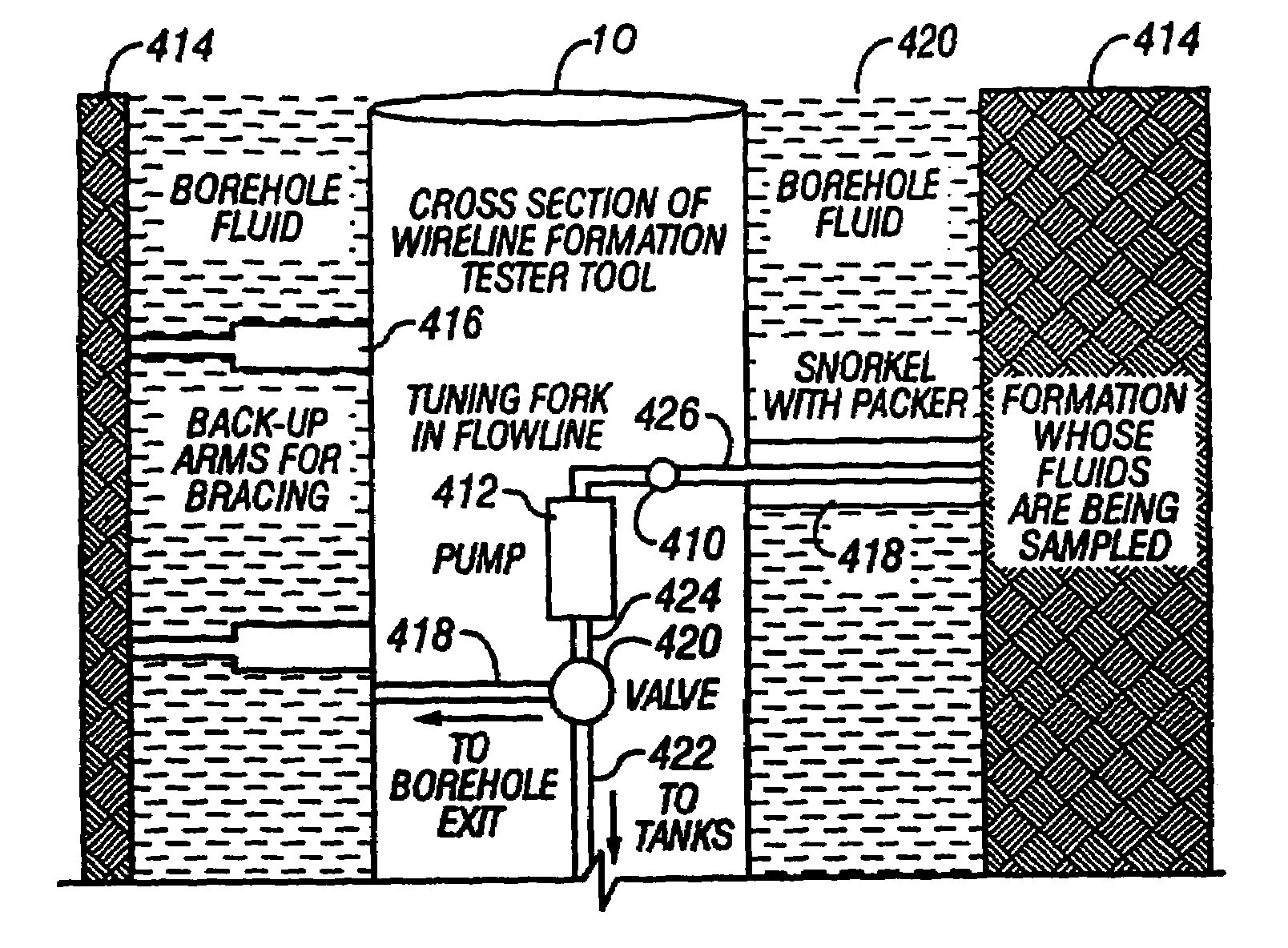
The present invention provides a downhole tool and method using a mechanical resonator to measure the viscosity, density, and dielectric constant of formation fluid or filtrate in a hydrocarbon producing well. The tool can also monitor cleanup from a leveling off of viscosity or density over time, measure the bubble point, dew point, and onset of asphaltene precipitation. The invention provides direct viscosity measurement capabilities that are currently unavailable in the oil services industry. The tool can also determine the characteristic of the fluid sample, such as the dew point, bubble point, or NMR decay times, which are used to estimate the density and pressure difference of the fluid. The invention also includes a plurality of pressure gauges to determine the density of the fluid. The mechanical resonator is made of quartz and has metallic electrodes deposited on its faces, and it can be placed in a cavity outside the direct flow path to protect it from damage. A hard or inorganic coating can also be placed on the flexural mechanical resonator to reduce its effects from abrasion.

Problems solved by technology

There is, however, no method or apparatus for measuring viscosity in the downhole environment.

Method used


Image

  • Method and apparatus for downhole fluid characterization using flexural mechanical resonators
  • Method and apparatus for downhole fluid characterization using flexural mechanical resonators
  • Method and apparatus for downhole fluid characterization using flexural mechanical resonators

Examples


Embodiment Construction

[0029]The inventors are aware of no method or apparatus for directly measuring density, viscosity or dielectric constant downhole using a flexural mechanical resonator. The present invention provides a downhole method and apparatus using a mechanical resonator, preferably, a tuning fork to provide real-time direct measurements and estimates of the viscosity, density and dielectric constant for formation fluid or filtrate in a hydrocarbon producing well. The present invention additionally provides a method and apparatus for: 1) monitoring cleanup from a leveling off of viscosity or density over time as the fluid under investigation transitions from contaminated to substantially pure formation fluid; 2) measuring or estimating bubble point for formation fluid; 3) measuring or estimating dew point for formation fluid; and 4) the onset of asphaltene precipitation. Each of these applications contribute to the commercial value of downhole monitoring while drilling and wire line tools, suc...


PUM

PropertyMeasurementUnit
frequency responsesaaaaaaaaaa
frequency responseaaaaaaaaaa

Abstract

The present invention provides a downhole method and apparatus using a flexural mechanical resonator, for example, a tuning fork to provide real-time direct measurements and estimates of the viscosity, density and dielectric constant of formation fluid or filtrate in a hydrocarbon producing well. The present invention additionally provides a method and apparatus for monitoring cleanup from a leveling off of viscosity or density over time, measuring or estimating bubble point for formation fluid, measuring or estimating dew point for formation fluid, and determining the onset of asphaltene precipitation. The present invention also provides for intercalibration of plural pressure gauges used to determine a pressure differential downhole. A hard or inorganic coating is placed on the flexural mechanical resonator (such as a tuning fork) to reduce the effects of abrasion from sand particles suspended in the flowing fluid in which the flexural mechanical resonator is immersed.

Description

CROSS REFERENCE TO RELATED APPLICATIONS[0001]This patent application is a Continuation in Part of U.S. patent application Ser. No. 10 / 144,965 filed on May 14, 2002 now U.S. Pat. No. 6,938,470 which claims priority from U.S. Provisional Patent Application Ser. No. 60 / 291,136 filed on May 15, 2001, both of which are hereby incorporated by reference in their entirety.BACKGROUND OF THE INVENTION[0002]1. Field of the Invention[0003]The present invention relates to the field of downhole fluid analysis in hydrocarbon producing wells. More particularly, the present invention relates to a method and apparatus for determining fluid density, viscosity, and other parameters using a flexural mechanical resonator downhole in a borehole during monitoring while drilling or wire line operations.[0004]2. Background of the Related Art[0005]There is considerable interest in obtaining density and viscosity for formation fluids downhole at reservoir conditions of extreme temperature and pressure during f...

Claims


Application Information

Patent Timeline
Patent Type & Authority Patents(United States)
IPC IPC(8): G01H3/04G01H3/14E21B41/00E21B47/10E21B49/10G01N9/00G01N11/16G01N33/24
CPCE21B47/10E21B49/10G01V3/32G01N33/24G01N9/002E21B2041/0028G01N11/16G01N2009/006E21B49/0875
Inventor DIFOGGIO, ROCCOWALKOW, ARNOLDBERGREN, PAULREITTINGER, PETER W.
Owner BAKER HUGHES INC
Learn More