Antenna for RFID

Inactive Publication Date: 2007-01-09
MITSUBISHI MATERIALS CORP
View PDF23 Cites 33 Cited by
  • Summary
  • Abstract
  • Description
  • Claims
  • Application Information

AI Technical Summary

Benefits of technology

[0008]In the case of an antenna for RFID of the present invention, the body of a coil is adjusted so that a predetermined characteristic value can be obtained when the body of the coil is wound on the surface of a conductive member. Therefore, it is possible to reliably activate a tag by transmitting radio waves at a predetermined frequency to the antenna for RFID from the transceiving (transmitting and / or receiving) antenna of an interrogator. Moreover, in the case of this antenna, because the body of the coil is already wound on the front of the conductive member and the predetermined characteristic value is obtained, the antenna is not influenced by the metal in an article to be managed even if the antenna is directly affixed to the article, and the characteristic value of the coil body is therefore not changed extremely. Thus, a spacer, which has required to affix an antenna to a metallic article, is unnecessary, and it is possible to avoid the tag greatly protruding from an article to be managed.
[0011]Moreover, it is possible to form a hole at a portion of the conductive member surrounded by the coil body and to set a soft magnetic member between the conductive member and coil body. When forming a hole on the conductive member corresponding the central portion of the coil body, even if an eddy current is generated on the conductive member due to radio waves passing through the coil body, the eddy current is generated in a small range close to the coil body, and thus, it is possible to prevent the Q value of the coil body from decreasing. Furthermore, when an object to be set is made of an insulating material or a material allowing electromagnetic waves to pass through, such as a metallic deposited film, it is also possible to use electromagnetic waves passing through the hole of the conductive member, and thereby, the sensitivity of the tag is improved. Alternatively, when setting a soft magnetic member between the conductive member and coil body, because magnetic fluxes of the electromagnetic waves flow through the soft magnetic member at a high density, a desired sensitivity can be obtained even if the interval between the conductive member serving as an electric conductor and the coil body serving as a coil is small. Moreover, it is allowed that the number of turns and / or spiral diameter of a coil for obtaining a predetermined inductance is small and the Q value is also improved.
[0013]In the case of the antenna for RFID of the second aspect of the present invention, by transmitting radio waves while setting the antenna on an article formed of metal, a soft magnetic member prevents radio waves from passing through a metallic portion and thereby, no eddy current is generated on the metallic portion. As a result, a tag is activated, a spacer has been previously required is unnecessary, and it is possible to prevent the antenna from contacting with a neighboring object when the article is transported.

Problems solved by technology

However, in the case of the above conventional tag, because the spacer has a relatively large thickness, the interval between the metallic article and tag becomes relatively large, even if the thickness of the antenna can be decreased, and a problem thereby occurs in that the tag greatly protrudes from the article to be managed.

Method used


Image

  • Antenna for RFID
  • Antenna for RFID
  • Antenna for RFID

Examples


experimental examples

[0040]Next, Experimental Examples of the present invention are described below in detail together with Comparative Examples.

experimental example 1

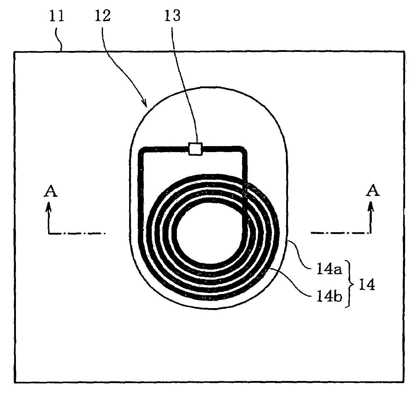
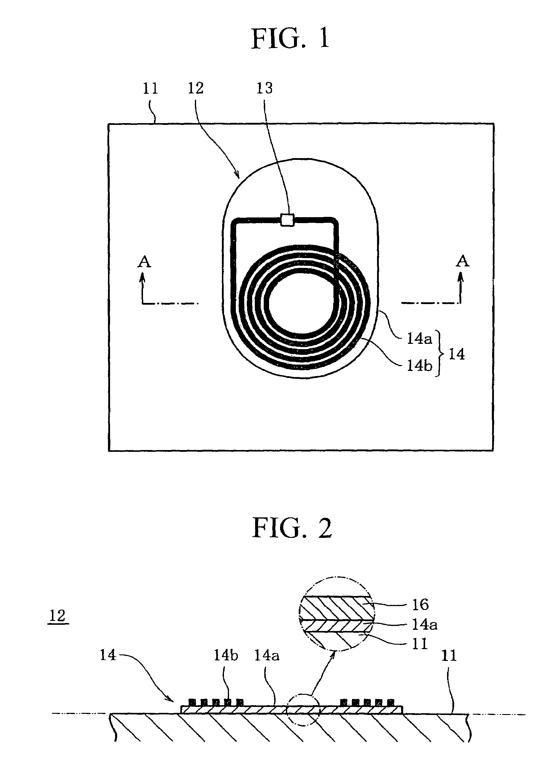
[0041]As shown in FIGS. 1 and 2, a coil body with an outer diameter of 50 mm and an inner diameter of 49 mm was made by winding a coated copper wire having a diameter of 0.2 mm four to five times. Moreover, a mild-steel plate having a size of 100×100 mm and a thickness of 0.16 mm was prepared as an article and a non-metallic acrylic plate having the same shape and size as the mild-steel plate was also prepared for comparison. As a conductive member, an aluminum plate having a size of 50×50 mm and a thickness of 0.2 mm was affixed to the surfaces of the mild-steel plate and acrylic plate, respectively. Then, the L1 value and the Q1 value of the coil body were measured by directly affixing the coil body at the surface of the aluminum plate which is affixed on the mild-steel plate, or by maintaining a predetermined interval to the surface of the aluminum plate. Thereafter, the values of L2 and Q2 were measured by directly affixing the coil body at the surface of the aluminum plate whic...

experimental example 2

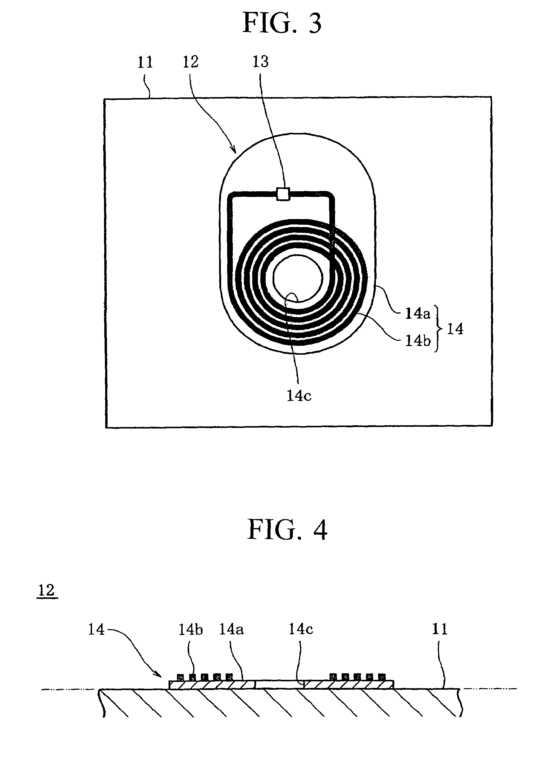
[0042]A soft magnetic member was set between the coil body and aluminum plate of the Experimental Example 1. The soft magnetic member used a member having an outer diameter of 60 mm and a thickness of 0.34 mm which was obtained by injection-molding a composite material made of 72% of carbonyl iron and polyethylene and then compressing the moulded composite material. The coil body of the Experimental Example 1 was brought into close contact with the surface of the soft magnetic member 26 to measure the L1 value and the Q1 value of the coil body by directly bringing the back of the soft magnetic member 26 into contact with the surface of an aluminum plate set on the mild-steel plate of the Experimental Example 1 or setting the soft magnetic member 26 by maintaining a predetermined interval. Then, the L2 value and the Q2 value of the coil body were measured by directly bringing the back of the soft magnetic member 26 into contact with the surface of the aluminum plate set on the acryli...


PUM


Abstract

An antenna for RFID (Radio Frequency Identification) configured to be electrically connected to an IC (Integrated Circuit) chip or capacitor and configured to be affixed to an article. The antenna includes: a planar conductive member having a first side configured to be mounted on the article; and a coil body configured with coil turns and mounted on or at a second side which is opposite to the first side of the conductive member. The number of the coil turns and diameter of the coil body are adjusted such that a characteristic of said coil body has a predetermined value. The conductive member shields the coil body from the article.

Description

[0001]This application is the National Phase International Application PCT / JP01 / 11078, filed Dec. 18, 2001.TECHNICAL FIELD [0002]The present invention relates to an antenna used for a tag using the RFID (Radio Frequency Identification) technique. More particularly, the present invention relates to an antenna for RFID which has a spiral coil and will be set to an article.BACKGROUND ART [0003]A tag is known which has an antenna and an IC chip, storing information about an article to be managed, electrically connected to the antenna, as a tag using the RFID technique. By transmitting radio waves at a predetermined frequency to the antenna from the transceiving antenna of an interrogator, the tag is activated, data is read from the IC chip in accordance with a read command through data communication by radio waves, and data is written in the IC chip in accordance with a write command. Moreover, a 1-bit RFID used for simplest EAS (Electronic Article Surveillance) is constituted by a capa...

Claims


Application Information

Patent Timeline
IPC IPC(8): H01Q1/24G06K19/07G06K19/077H01F1/12H01F1/147H01F1/153H01Q1/22H01Q1/38H01Q7/00H01Q7/06H01Q9/27H04B1/59H04B5/02
CPCG06K19/0726G06K19/07749G06K19/07771G06K19/07779G06K19/07781H01Q9/27H01Q1/22H01Q1/2225H01Q1/38H01Q7/00H01Q7/06G06K19/07783
Inventor ENDO, TAKANORIYONEZAWA, TADASHIYAHATA, SEIROU
Owner MITSUBISHI MATERIALS CORP
Why Eureka
Try Eureka