High power ultrasonic reactor for sonochemical applications

Inactive Publication Date: 2007-01-02
NANO SIZE
View PDF9 Cites 348 Cited by
  • Summary
  • Abstract
  • Description
  • Claims
  • Application Information

AI Technical Summary

Benefits of technology

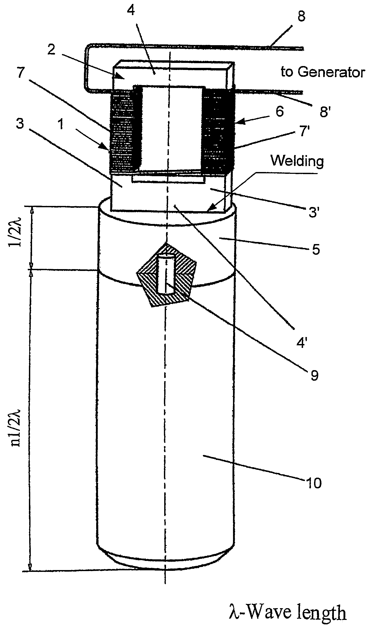
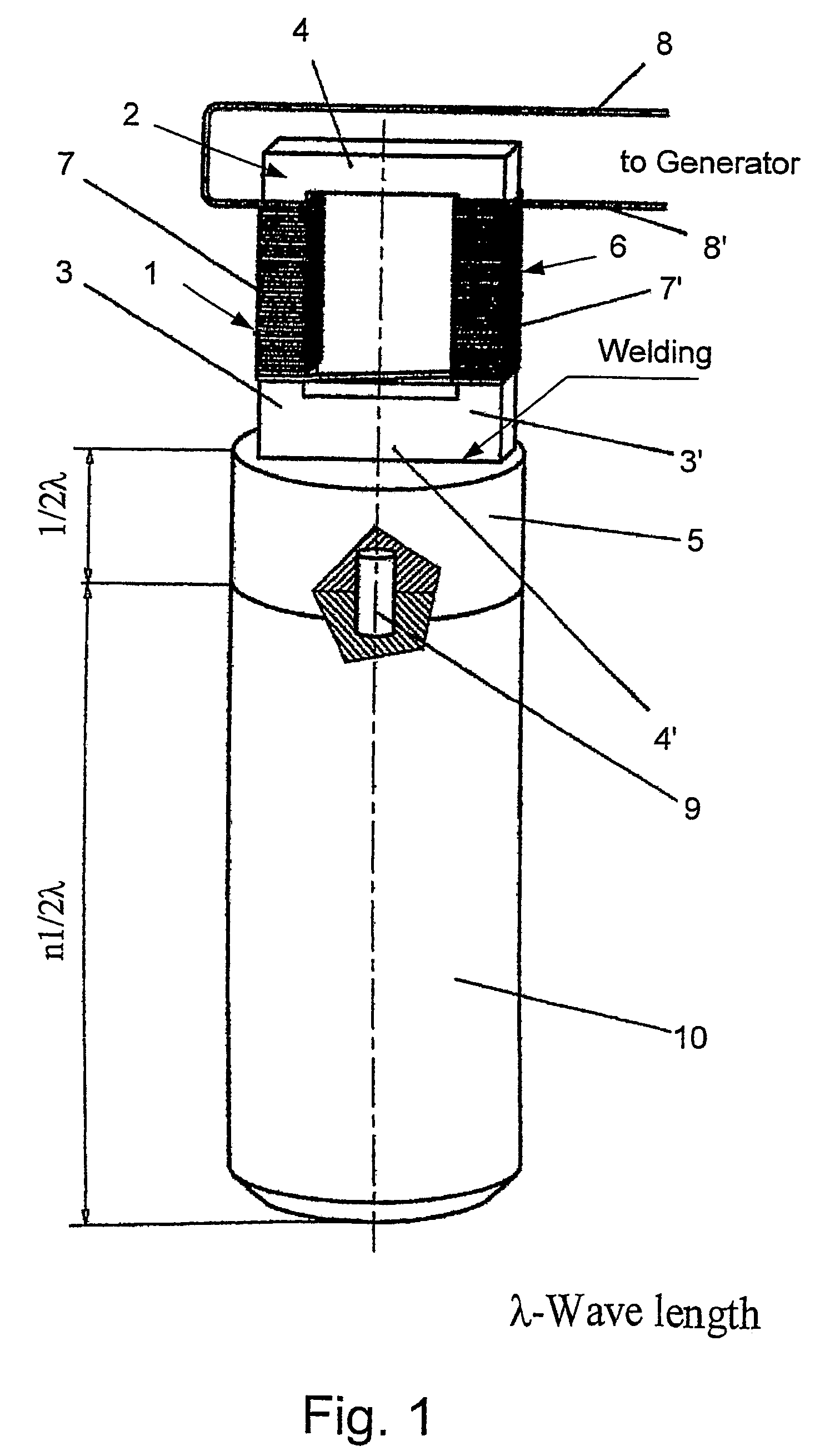
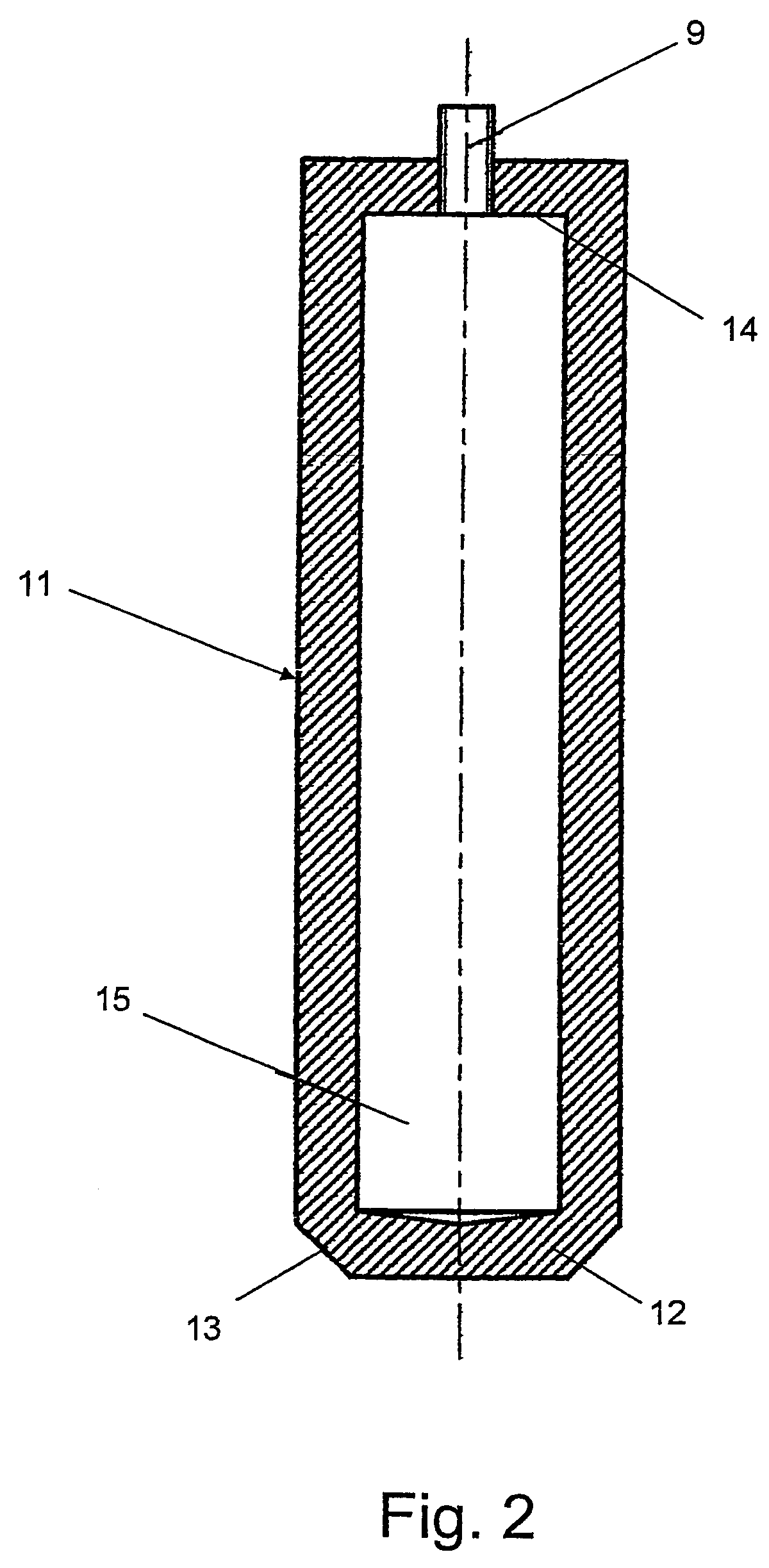
[0038]The horn of this invention, contrary to prior art horns, is of a hollow resonant type (see FIG. 2). The length of the horn is resonant, namely it is equal to half a wavelength or several half wavelengths in the horn material. Said horn is additionally characterized by an internal resonant cavity, consisting of several advantageous functions: 1) Said cavity reduces the thickness of the horn walls, thereby increasing the ease of horn wall motion and amplitude with a given driving force; 2) Said cavity causes an uneven transmittance of transducer power to the horn, forming a standing wave that forces the horn walls to vibrate; 3) Said cavity increases the horn vibrations through resonance that is the result of interaction between parallel vibrating walls. In a first embodiment of the invention, the shape of said cavity matches the outer shape of the horn, defining a uniform horn wall thickness. Therefore, since the horn is preferably cylindrical, the cavity is preferably of a cylindrical shape. In a second embodiment of the invention, said cavity comprises a plurality of cylindrically shaped sections, preferably equivalent, thereby providing additional advantages that will be explained hereinafter.
[0041]The ultrasonic power generated by the transducer of the invention is emitted outwardly from the entire surface of the horn, comprising its sides, and not merely from its extremity, as in prior art horns. In the prior art horns, the only emitting surface is a narrow extremity and the ultrasonic waves spread out from it in a conical configuration; therefore the ultrasound has a high intensity at said extremity and becomes weaker as it spreads out from it, roughly inversely proportional to the square of the distance from said extremity. In the horn of the present invention the irradiating surface is practically the entire outer surface of the horn and the ultrasound intensity is substantially uniform throughout the reaction space, although it is still somewhat higher at the horn extremity, as will be explained hereinafter. This leads to a greatly increased efficiency, on the order of 60–80%, as has been said.
[0043]The generated acoustic standing wave in the reactor volume, which operates as a hollow resonator, in combination with uniform emission of ultrasound from the surface of the horn as well as from its extremity, provides homogeneous distribution of ultrasonic energy over the reactor volume.

Problems solved by technology

The principal drawback of the aforementioned technique is non-homogeneous distribution of ultrasonic energy inside a reaction volume in longitudinal and transversal directions that leads to inefficient sonochemical reactions.
The disadvantage is in the limited volume in which acoustic cavitation, hence chemical reaction, takes place.
The application of multiple transducers is used by Dion, U.S. Pat. No. 6,361,747, where multiple transducers are operating at a phase shift from one another, leading to inefficient and non-homogeneous ultrasonic energy coupling that arises from the interference of oscillations with phase deviations.
Such reactors cannot be applied for efficient sonochemical processes, particularly for nano-particle production, which demand an essentially homogeneous distribution of ultrasonic energy throughout the reaction volume.
An additional drawback of the ultrasonic device described by Dion U.S. Pat. No. 6,361,747 is the following: for full energy transmission, it is necessary to provide very tight acoustic contact between ends (edges) of segmental radiators and tube surface, as well as between waveguide and acoustic transducer.
The implementation of acoustic contact leads to high-energy losses and to conversion of this energy into high amounts of heat.
Piezo-electric transducers, however, have a maximum power not more than 2 kW and a low oscillation amplitude dictated by the fragility of piezo-electric elements, which can be destroyed under prolonged operation.
They are also not reliable compared to magnetostrictive transducers, to be described hereinafter, because their amplitude drifts under operation, causing transducer failure and lower energy output, leading to operation parameters that must be manually corrected.
At their area of maximum intensity various phenomena occur, including heating, cavitation, evaporation, and so on, which absorb and waste a large portion of the ultrasonic energy, resulting in a process of low efficiency (ratio of power spent for required process to overall power), which is generally on the order of 20–30%.

Method used


Image

  • High power ultrasonic reactor for sonochemical applications
  • High power ultrasonic reactor for sonochemical applications
  • High power ultrasonic reactor for sonochemical applications

Examples


example 1

Production of Nano Iron Hydroxide Powder

[0075]The iron hydroxide is produced from an iron salt, in this example iron chloride, and a base, particularly an alkali hydroxide, in this example sodium hydroxide, according to the following reaction:

2FeCl3+6NaOH→2Fe(OH)3+6NaCl

[0076]The reagents are prepared by weighing with an analytical balance and preparing water solutions of iron chloride and sodium hydroxide.

[0077]The reaction is carried out under high power ultrasound according to the following parameters:

[0078]Reaction composition: iron chloride—80 gr.[0079]1. sodium hydroxide—60 gr.[0080]2. distilled water—950 gr.

[0081]Time of reaction—5 minutes

[0082]The product is Nano iron hydroxide powder, having particle size below 100 nm.

example 2

Production of Nano-Amorphous Nickel Hydroxide Ni(OH)2

[0083]The nickel hydroxide is produced from a nickel salt, in this example nickel chloride, and a base, in this example sodium hydroxide, according to the following reaction:

NiCl2+2NaOH→Ni(OH)2+2NaCl

[0084]The reagents are prepared by weighing with analytical balance and preparing water solutions of nickel chloride and sodium hydroxide.

[0085]The reaction is carried out according to the following parameters:

[0086]Reaction volume—1 liter

[0087]Reaction composition: nickel chloride—70 g[0088]a. sodium hydroxide—25 g[0089]b. distilled water—900 ml

[0090]Time of reaction—5 minutes

[0091]The product nickel hydroxide is a green amorphous material having surface area (BET)>350 m2 / gr and particle size (HRSEM) of 20–60 nm.

example 3

Production of Nano-Crystalline Cobalt Powder

[0092]The cobalt is produced from a cobalt salt, in this example cobalt chloride, and a powder of a metal capable of reducing said salt to cobalt metal (hereinafter indicated by “M”), according to the following reaction:

CoCl2+M→Co+MCl2

[0093]The reaction is carried out according to the following parameters:

[0094]Reaction volume—1 liter

[0095]Reaction composition: cobalt chloride—240 g[0096]a. M—reducing metal[0097]b. suitable solvent—1 liter

[0098]Time of reaction—5 minutes

[0099]The product is hexagonal cobalt powder, having a specific weight of 8.9 g / cc and a black color, and particle size 10–40 nm.

[0100]Other metals can be produced by similar reactions.


PUM

PropertyMeasurementUnit
Poweraaaaaaaaaa
Lengthaaaaaaaaaa
Diameteraaaaaaaaaa

Abstract

Ultrasound device having a reaction chamber, which includes a magnetostrictive transducer and a horn transmitting ultrasound radiation substantially uniformly throughout the reaction chamber. The horn is hollow and is constituted by a cylinder having an empty inner chamber at its core defining a resonance chamber, which may be cylindrical and may comprise a plurality of sections of cylindrical shape or a central section of larger diameter and two terminal sections of smaller diameter.

Description

RELATED APPLICATION[0001]This application is a continuation of International Application PCT / IL02 / 00560, filed Jul. 11, 2002, the contents of which are here incorporated by reference in their entirety; priority is claimed under 35 USC 120.BACKGROUND OF THE INVENTION[0002]1. Field of the Invention[0003]The present invention relates to an improved ultrasonic generating and radiating device for use in a sonochemical reactor. More particularly, the invention relates to a device comprising transducers, preferably of the magnetostrictive type, and horns (sonotrodes) that emit ultrasound to the entire volume of a reactor containing liquid, wherein the distribution of ultrasonic energy and acoustic cavitation is homogeneous throughout the reactor volume, leading to an increase in the efficiency of sonochemical processes.[0004]2. Prior Art[0005]Ultrasonic energy has many applications in present-day technology in physical and chemical processes. Some general references are:[0006]1) K. S. Susl...

Claims


Application Information

Patent Timeline
IPC IPC(8): B06B1/00B01J8/40B01J19/00B01J19/10B06B3/00B22F1/054B22F9/24C01B13/36C01G49/06C01G53/02C09C1/24
CPCB01J8/40B01J19/10C09C1/24B06B3/00B22F1/0018B22F9/24B82Y30/00C01B13/36C01G49/06C01G53/02C01P2006/60B01J2219/0877B01J2219/0879B22F2999/00C01P2004/64C01P2006/10C01P2006/12B22F2202/01B22F1/054
Inventor MARHASIN, EVGENYGRINTZOVA, MARINAPEKKER, VICKTORMELNIK, YURI
Owner NANO SIZE
Why Eureka
Try Eureka