
Digitally controlled modular power supply for automated test equipment

a technology of digital control and modular power supply, applied in the direction of motor/generator/converter stopper, dynamo-electric converter control, instruments, etc., can solve the problems of large power dissipation by the supply, increased cost and size of the power supply, and limited output voltage, so as to achieve both efficiency and flexibility

Inactive Publication Date: 2006-12-26
ADVANTEST CORP
View PDF9 Cites 16 Cited by
  • Summary
  • Abstract
  • Description
  • Claims
  • Application Information

AI Technical Summary

Benefits of technology

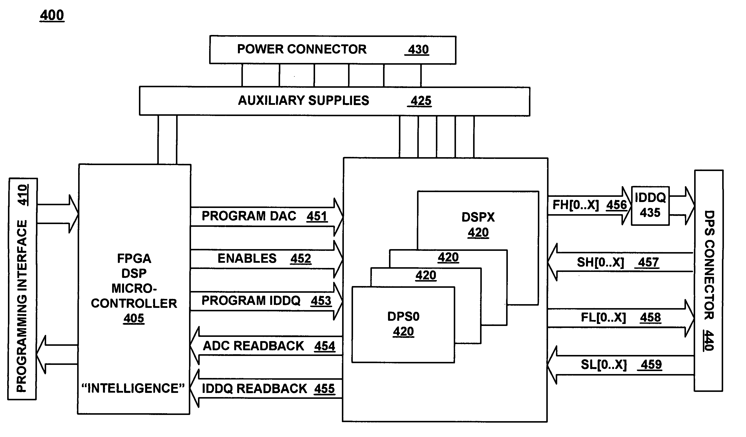
The present invention provides an improved device power supply (DPS) that offers both efficiency and flexibility for powering integrated circuits over a wider range of current and voltage requirements. This is achieved by combining firmware programmability and hardware. The DPS can be used in automatic test equipment (ATE) applications. The invention includes a digitally controllable hybrid power module that allows for independent adjustment of its output voltages using a switching power supply and a linear voltage regulator. The hybrid power module also includes switches for enabling / disabling functionality and uses output voltage transient suppression and current limiting to control transients. The invention also includes a programmable controller that can independently control one or more power modules and provide protection features in firmware.

Problems solved by technology

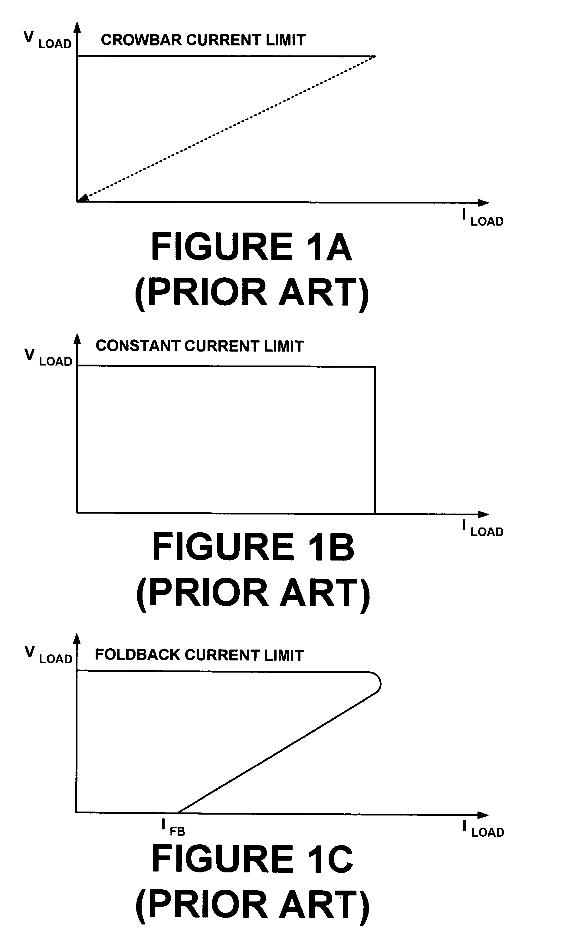
The constant current scheme allows for continued operation of the device being tested at the set maximum current; however, the power supply may be required to sustain a large voltage drop across its pass device, resulting in a large power dissipation by the supply.
The requirement for handling the thermal load increases the cost and size of the power supply.
Although operation can be maintained at a reduced current, foldback limiting can have difficulty recovering from a short circuit, with the output voltage being limited if the load current rises above Ifb.
The current limit cannot be easily adjusted without circuit modification.
This problem is exacerbated when a low voltage part requires more current than its higher voltage counterpart, which is typically the case.

Method used


Image

  • Digitally controlled modular power supply for automated test equipment
  • Digitally controlled modular power supply for automated test equipment
  • Digitally controlled modular power supply for automated test equipment

Examples


Embodiment Construction

[0028]Reference will now be made in detail to the embodiments of the invention, digitally controlled modular power supplies for Automatic Test Equipment (ATE), examples of which are illustrated in the accompanying drawings. While the invention will be described in conjunction with the preferred embodiments, it will be understood that they are not intended to limit the invention to these embodiments. The invention is intended to cover alternatives, modifications and equivalents, which may be included within the spirit and scope of the invention as defined by the appended claims. Furthermore, in the following detailed description of the present invention, numerous specific details are set forth in order to provide a thorough understanding of the present invention. However, it will be obvious to one of ordinary skill in the art that the present invention may be practiced without these specific details. In other instances, well known methods, procedures, components, and circuits have no...


PUM


Abstract

A digitally controlled hybrid power module is controlled by a programmable controller. The hybrid power module includes a digitally controlled switching supply with an output coupled to an input of a digitally controlled linear voltage regulator. Independent control of switching supply and the linear regulator is provided by the programmable controller, which may be a field programmable gate array (FPGA), microcontroller, or digital signal processor (DSP). The programmable controller may independently control one or more power modules. Each power module may also include enable switching and an associated current clamp for capacitive loads. An output voltage transient suppressor may also be used to control transients, such as those produced under fast switching conditions.

Description

RELATED APPLICATIONS[0001]This application is a divisional of and claims priority to U.S. Pat. Ser. No. 10 / 613,848 now U.S. Pat. No. 6,900,621, entitled “Digitally Controlled Modular Power Supply For Automated Test Equipment,” by Gunther, filed on Jul. 3, 2003, which is incorporated herein by reference.FIELD OF THE INVENTION[0002]The present invention relates to automatic test equipment (ATE) systems used to test integrated circuits (ICs). More specifically, the invention is directed to device power supplies (DPS) for providing power to circuits under test.BACKGROUND ART[0003]Automated test equipment (ATE) for digital integrated circuits are required to provide a stimulus to the integrated circuit (IC) and to measure the resultant digital response from the IC. Depending upon the size and function of the IC being tested, the power required for testing common ICs may range from less than one watt to greater than 50 watts. In order to meet the wide range of current and voltages require...

Claims


Application Information

Patent Timeline
Patent Type & Authority Patents(United States)
IPC IPC(8): G05F1/573G05F1/40G05F1/44G05F1/56G05F1/618H02J3/00H02M5/40G05F1/563
CPCG05F1/573
Inventor GUNTHER, ANDRE
Owner ADVANTEST CORP
Learn More