
Method for adjusting data insertion degree and data insertion circuit

a data insertion circuit and data technology, applied in the field of data insertion circuit and data insertion method, can solve the problems of forming damaged mpeg2 data, conventional data insertion circuits cannot be adopted to a system, and the inability to detect inserted data, so as to increase the insertion degree and reduce the threshold value

Inactive Publication Date: 2006-12-19
NEC PERSONAL COMPUTERS LTD
View PDF9 Cites 0 Cited by
  • Summary
  • Abstract
  • Description
  • Claims
  • Application Information

AI Technical Summary

Benefits of technology

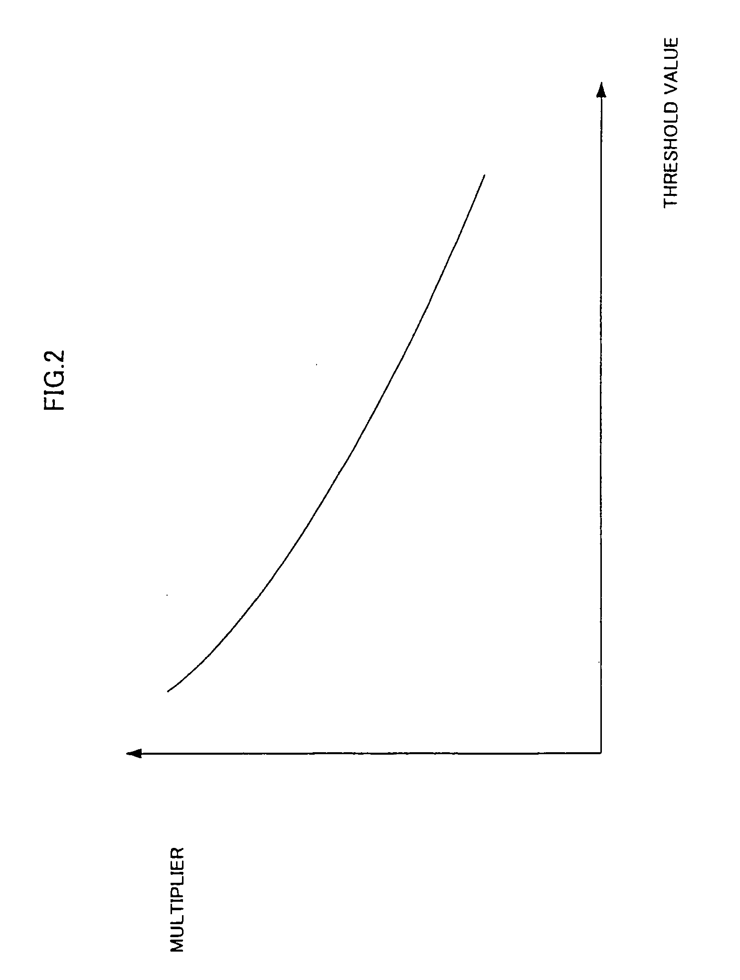
[0060]The comparison circuit may increase the insertion degree and decreases the threshold value, in a case where a value, obtained by dividing the number counted by said second counter by a number counted by said first counter, is smaller than the threshold value.
[0062]The comparison circuit may increase the insertion degree and decreases the threshold value, in a case where a value, obtained by dividing the number counted by said second counter by a number counted by said first counter, is smaller than the threshold value.
[0063]The comparison circuit may increase the insertion degree and decreases the threshold value, in the case where the proportion N3 / NA is smaller than the threshold value.

Problems solved by technology

Hence, if the MPEG2 data which is variable-length coded is used as is, the data length of the entire MPEG2 data may change, resulting in forming damaged MPEG2 data.
However, depending on the original MPEG2 data, the inserted data may not be detected.
1) insert the data into the image data;
2) pass output data to a detector, and check whether the inserted data can be detected; and
3) increase an insertion degree (increase a value of the data to be inserted) and try to insert the data again, if the data could not be detected. The conventional data insertion circuit can not be adopted to a system which executes the insertion process in real time.
None of the above techniques include a system for executing the insertion process in real time.

Method used


Image

  • Method for adjusting data insertion degree and data insertion circuit
  • Method for adjusting data insertion degree and data insertion circuit
  • Method for adjusting data insertion degree and data insertion circuit

Examples


first embodiment

[0081]A data insertion circuit according to the present invention will now be explained with reference to the accompanying drawings.

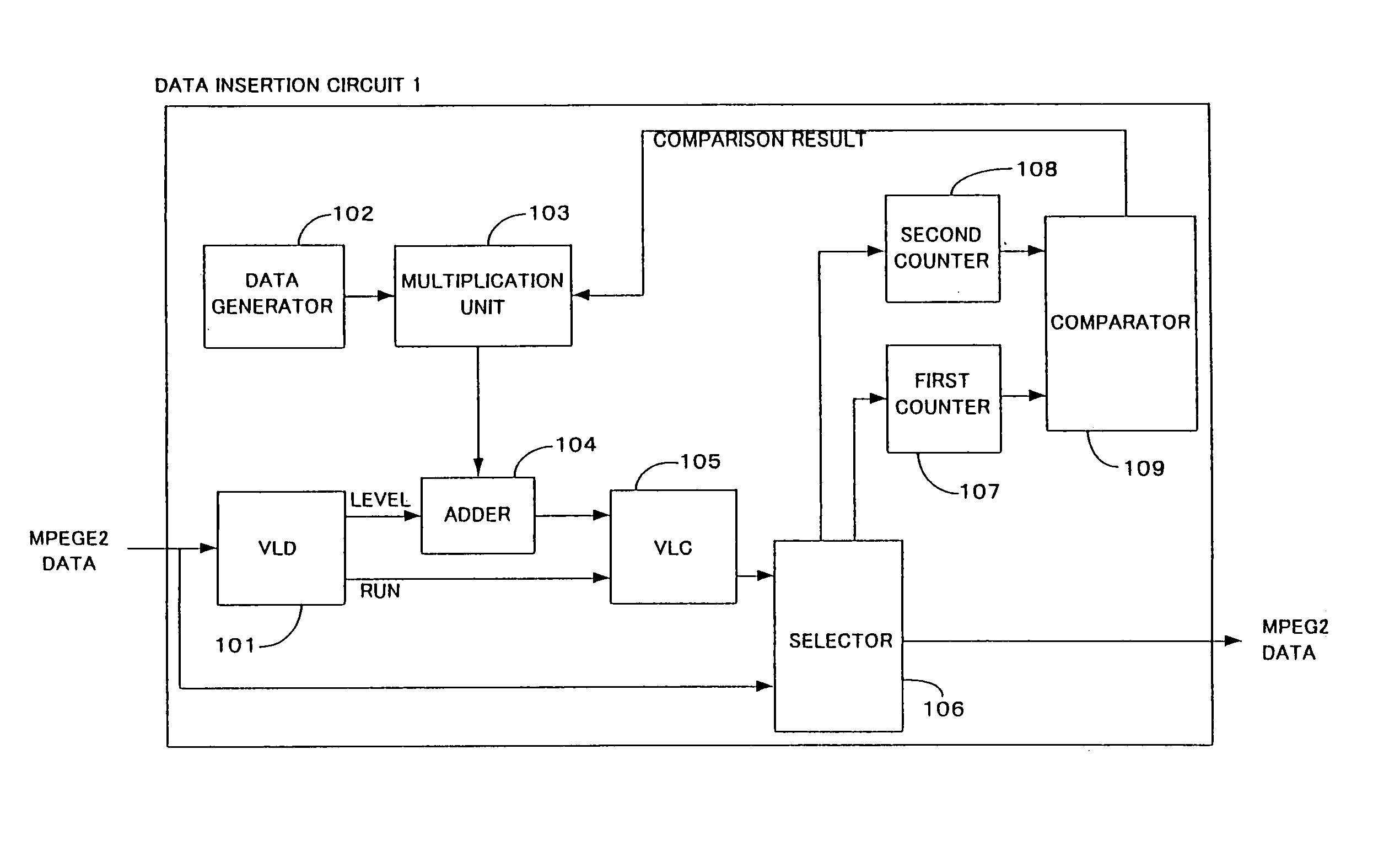
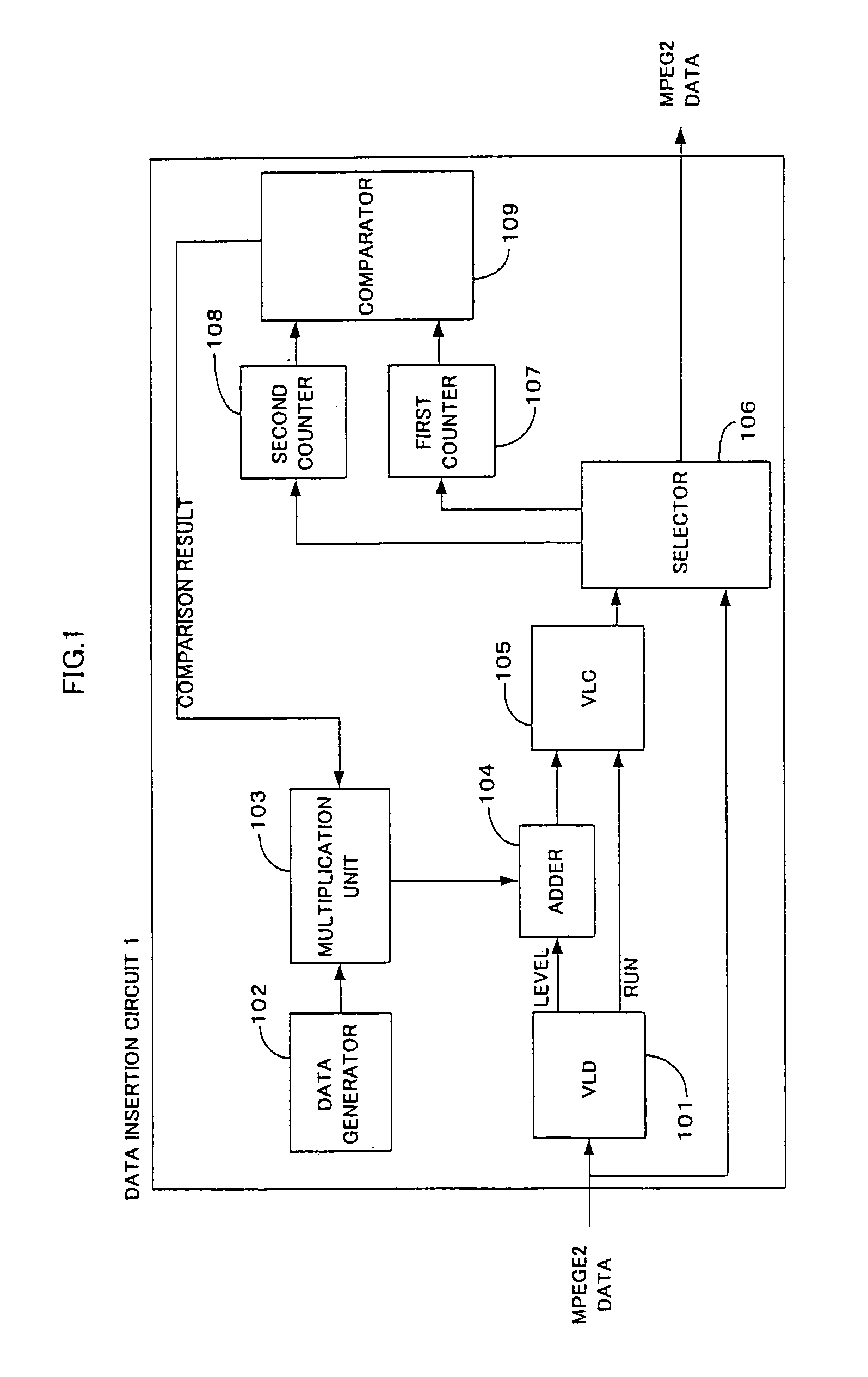
[0082]As shown in FIG. 1, a data insertion circuit 1 comprises a VLD (Variable Length Decoder) 101, a data generator 102, a multiplication unit 103, an adder 104, a VLC (Variable Length Coder) 105, a selector 106, the first counter 107, the second counter 108, and a comparator 109.

[0083]The VLD 101 variable-length decodes image data, in the format of MPEG2 standard, which is sent from an external circuit, so as to generate a RUN and Level from the image data.

[0084]The data generator 102 generates data to be inserted into the image data into the MPEG2 data.

[0085]The multiplication unit 103 multiplies the data generated by the data generator 102 by a predetermined value α (=insertion degree or insertion intensity).

[0086]The adder 104 adds the Level output by the VLD 101 to data (target data to be inserted) output by the multiplication unit 103.

[0087]The V...

second embodiment

[0102]A data insertion circuit 2 according to the present invention will now be explained with reference to FIG. 4.

[0103]In FIG. 4, the multiplication unit 103 multiplies the inserted data, which is output from the data generator 102, by an insertion degree β output from the comparator 109, and sends a multiplied result to the adder 104. Likewise the first embodiment, the VLD 101 variable-length decodes the MPEG2 data is variable / length, so as to generate a Level and RUN.

[0104]The adder 104 adds data to the Level output from the VLD 101, and the VLC 105 variable-length codes the data including the data inserted thereto. The selector 106 selects data output by the VLC 105, only if the code length (the data length) of the data output by the VCL, 105 coincides with the code length of the original MPEG2 data. On the contrary, the selector 106 selects the original MPEG2 data, if the code lengths do not coincide with each other.

[0105]The first counter 107 shows the number of times the sel...


PUM


Abstract

A VLD decodes MPEG2 data so as to generate RUN and Level therefrom. A multiplication unit multiplies target data to be added to the Level, and sends a multiplied result to an adder. The adder adds the target data to the Level. The VLC codes the MPEG2 data, using the RUN and the Level to which the target data is added. The selector compares the data length of the MPEG2 data which has been decoded by the VLC with the data length of the original MPEG2 data. If those data lengths coincide with each other, the selector selects the MPEG2 data output by the VLC. On the contrary, if those data lengths do not coincide with each other, the selector selects and outputs the original MPEG2 data. A counter counts the number of times the selector has done the selection, while another counts the number of times the selector has selected the data output by the VLC. The comparator compares the counted values of both of the counters, and adjusts the insertion degree based on a result of the comparison.

Description

BACKGROUND OF THE INVENTION[0001]1. Field of the Invention[0002]The present invention relates to a data insertion circuit and data insertion method for inserting data into compressed image data, etc.[0003]2. Description of the Related Art[0004]Conventionally, data insertion circuits have been used for inserting data, including a digital watermark, etc., into compressed digital image data.[0005]The structure of a conventional data insertion circuit will be described with reference to FIG. 6.[0006]A data insertion circuit 3 shown in FIG. 6 is prepared for inserting predetermined data into digital image data which has been compressed according to the MPEG-2 (Moving Pictures Experts Group 2) standard. A VLD (Variable Length Decoder) 101 decodes data which has been variable-length coded. A data generator 102 generates data to be inserted into the compressed image data. A multiplication unit 103 adjusts an insertion degree at which the target data to be inserted is inserted into image dat...

Claims


Application Information

Patent Timeline
Patent Type & Authority Patents(United States)
IPC IPC(8): G06K9/00G06T9/00H04N19/00H04N7/08H04N7/081H04N19/102H04N19/134H04N19/196H04N19/467H04N19/70H04N19/91
CPCG06T9/007
Inventor SATO, SHINOBU
Owner NEC PERSONAL COMPUTERS LTD
Learn More