
Concentrated winding stator coil for an electric rotary machine

a technology of electric rotary machines and stator coils, which is applied in the direction of windings, dynamo-electric components, synchronous machines, etc., can solve the problems of large bus bar accommodation space, difficult to perform such a wire connection work near the tooth coils or slots, and the possibility of the wires touching the rotor, etc., to achieve a simple and highly densified fashion.

Inactive Publication Date: 2006-12-12
DENSO CORP
View PDF9 Cites 10 Cited by
  • Summary
  • Abstract
  • Description
  • Claims
  • Application Information

AI Technical Summary

Benefits of technology

The present invention provides a concentrated winding stator coil for an electric rotary machine that is compact and lightweight, with excellent cooling and insulation properties. The coil includes tooth coils with two layers of winding, crossover bus bars, and neutral bus bars that are placed close to the core back of the stator. The lead wires extend outward in a radial direction from the tooth coil and are connected to the crossover and neutral bus bars. The arrangement of the crossover and neutral bus bars helps to minimize resistance loss and facilitate wiring. The use of the proximal end extraction type two-layer winding stator coil and the close proximity of the crossover and neutral bus bars to the core back also reduces the axial length of the stator and simplifies the accommodation of the bus bars.

Problems solved by technology

First, in the process of arranging a phase winding by connecting tooth coils of the same phase via crossovers in serial or parallel to each other, at least one end of each tooth coil is positioned at the distal end portion of the tooth. In the case of using short crossovers, the crossovers or lead wires extending from end portions of the tooth coils and connected to the crossovers will be positioned very closely to the cylindrical surface of a rotor. If these wires are loosened and subjected to vibrations, there will be the possibility that the wires contact with the rotor.
Performing such a wire connection work near the tooth coils or slots is not easy.
These problems are especially serious when a conductor having a large cross-sectional area is used for the tooth coil, because it is necessary to use a comparable conductor having an equivalent cross-sectional area for the crossover intervening between the tooth coils or lead wires of respective tooth coils.
As a result, a large bus bar accommodation space is required.
Furthermore, due to damage or deterioration of a resin coating film of the tooth coil conductor, the possibility of lessening electric insulation properties between neighboring turns of each tooth coil will greatly increase.
Furthermore, coating a thin tooth coil conductor with a resin film and winding this coil conductor densely around a tooth is not preferable in assuring satisfactory cooling properties for the coil conductor positioned deeply in the layers of turns.
Namely, the resin coating film of respective tooth coils and numerous clearances between adjacent turns will increase the heat transfer resistance so greatly that large current cannot be supplied to the tooth coil.
As a result, the electric rotary machine undesirably increases its size.
However, in this case, the cross-sectional area of the tooth coil conductor becomes very larger.
As a result, the electric rotary machine undesirably increases its size.

Method used


Image

  • Concentrated winding stator coil for an electric rotary machine
  • Concentrated winding stator coil for an electric rotary machine
  • Concentrated winding stator coil for an electric rotary machine

Examples


first embodiment

Overall Structure

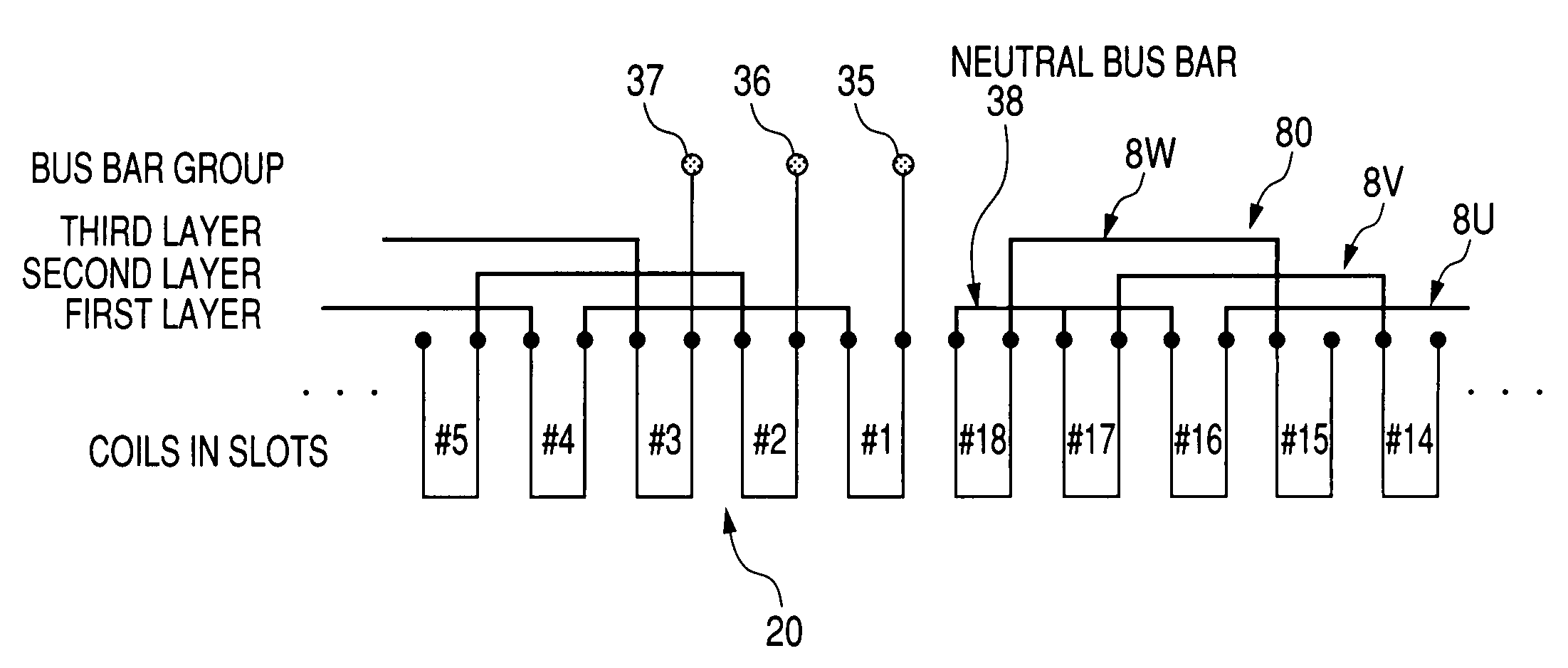
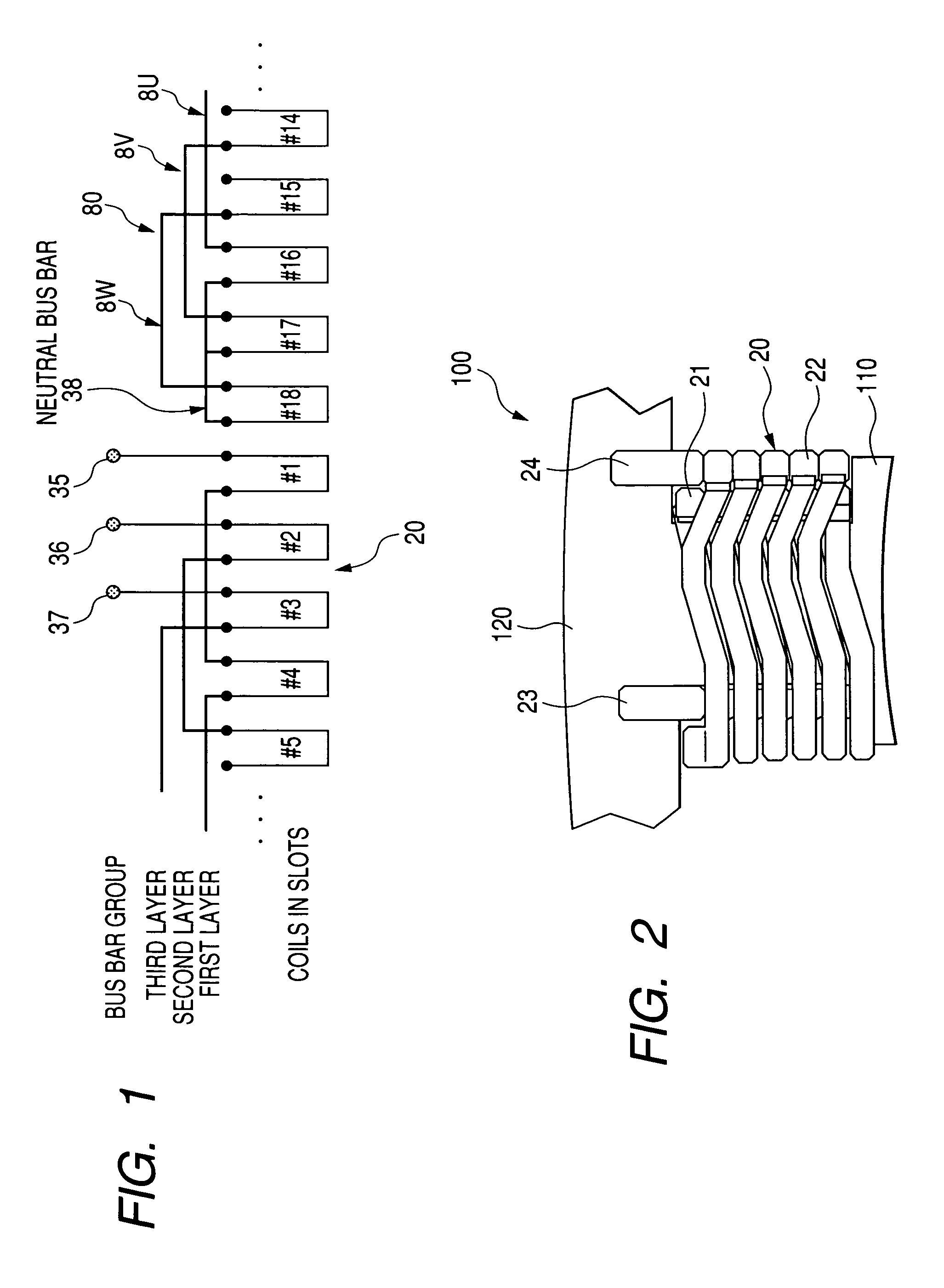
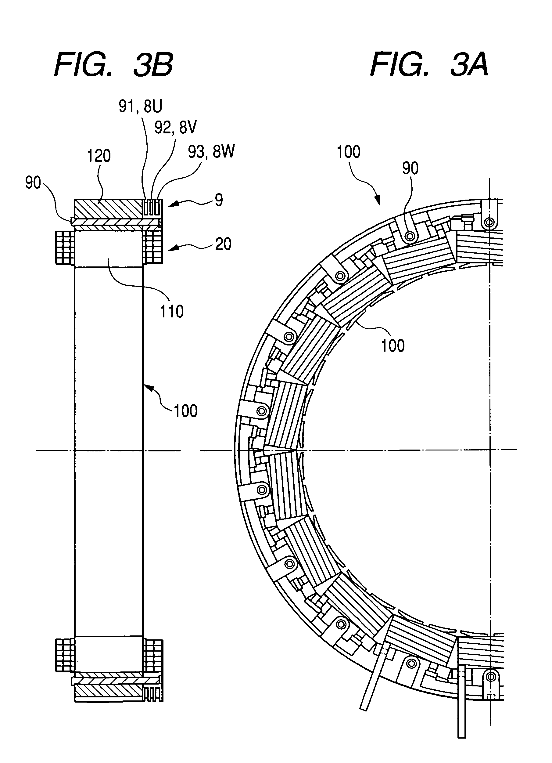
[0045]A concentrated winding stator having proximal end extraction type two-layer winding coils in accordance with a first embodiment of the present invention will be explained with reference to FIG. 1 showing a wiring arrangement, FIG. 2 showing an enlarged front view of a tooth and its periphery, FIG. 3A partly showing a front view of the stator, FIG. 3B showing a side cross-sectional view of the stator, and FIG. 4 partially showing an enlarged front view of a bus holder. A stator core 100 consists of a total of 18 teeth 110 and a single core back 120. The stator core 100 is arranged by multilayered electromagnetic steel plates. The stator core 100 has an assembled core structure, although FIG. 2 does not show the details of the assembled core structure.

[0046]Each tooth 110 protrudes inward in the radial direction from an inner cylindrical surface of the core back (i.e. yoke) 120. The teeth 110 are disposed at constant angular pitches in the circumferential direct...

second embodiment

[0060]A second embodiment of the present invention will be explained with reference to FIGS. 5A and 5B. FIG. 5A is a front view of a concentrated winding stator including proximal end extraction type two-layer winding coils in accordance with the second embodiment. FIG. 5B is a cross-sectional view of the stator shown in FIG. 5A, taken along a plane extending in an axial direction. This embodiment is different from the above-described first embodiment in the arrangement of three-phase crossover bus bars. More specifically, according to this embodiment, the three-phase crossover bus bars are offset in the radial direction in a predetermined phase order. And, the crossover bus bars of the same phase are disposed at same positions in both axial and radial directions. On the other hand, according to the first embodiment, the three-phase crossover bus bars are offset in the axial direction in a predetermined phase order. And, the crossover bus bars of the same phase are disposed at same ...

third embodiment

[0063]A third embodiment of the present invention will be explained with reference to FIG. 6. FIG. 6 is an enlarged cross-sectional view showing a crossover bus bar group 80 of a concentrated winding stator including proximal end extraction type two-layer winding coils according to this embodiment, taken along the axial direction.

[0064]This embodiment shows a modified example of the second embodiment which is characterized in that the crossover bus bars of each phase are offset in the radial direction in a predetermined phase order. According to this embodiment, respective bus bars consisting of the crossover bus bar group 80 and the neutral bus bar 38 (shown in the first embodiment) are flat type wires which have the cross section identical with that of the tooth coil 20 and are preferably sheathed with a resin coating film, and are formed by elongating the lead wires 23 and 24 extending from the tooth coils 20.

[0065]According to this embodiment, the radial width of the core back 1...


PUM


Abstract

A first layer coil is wound around the surface of a tooth in a direction advancing from a proximal end portion to a distal end portion of this tooth. A second layer coil is wound on the first layer coil in a direction advancing from the distal end portion to the proximal end portion of the tooth coil. Lead wires extend outward in the radial direction from a winding start end of the first layer coil and a winding terminal end of the second layer coil. Respective tooth coils of the same phase are serially connected to arrange three phase windings. A crossover bus bar group is accommodated in a space having a square cross section defined by a core back and a coil end of the tooth coil.

Description

CROSS-REFERENCE TO RELATED APPLICATION[0001]This application is based upon and claims the benefit of priority from earlier Japanese Patent Application No. 2004-125767 filed on Apr. 21, 2004 so that the descriptions of which are incorporated herein by reference.BACKGROUND OF THE INVENTION[0002]The present invention relates to a concentrated winding stator coil for an electric rotary machine.[0003]A concentrated winding stator, conventionally proposed in the field of electric rotary machines, includes a plurality of phase windings each consisting of same phase coils connected with each other and wound in a concentrated manner around respective teeth of a stator core (hereinafter, referred to as tooth coils). From requirements of the winding work, this kind of concentrated winding stator is generally used for an assembled core which is formed by assembling separated partial cores of respective teeth into a stator core.[0004]The tooth coils of a concentrated winding stator are wound aro...

Claims


Application Information

Patent Timeline
Patent Type & Authority Patents(United States)
IPC IPC(8): H02K3/18H02K3/52H02K1/00H02K3/28H02K3/46H02K15/095H02K21/00
CPCH02K3/522H02K2203/09
Inventor YONEDA, SHIGENORIYOSHINAGA, SOICHI
Owner DENSO CORP
Learn More