Exhaust purification device and exhaust purification method of internal combustion engine
- Summary
- Abstract
- Description
- Claims
- Application Information
AI Technical Summary
Benefits of technology
Problems solved by technology
Method used
Image
Examples
Embodiment Construction
[0036]Preferred embodiments of the present invention will be described in detail below while referring to the attached figures.
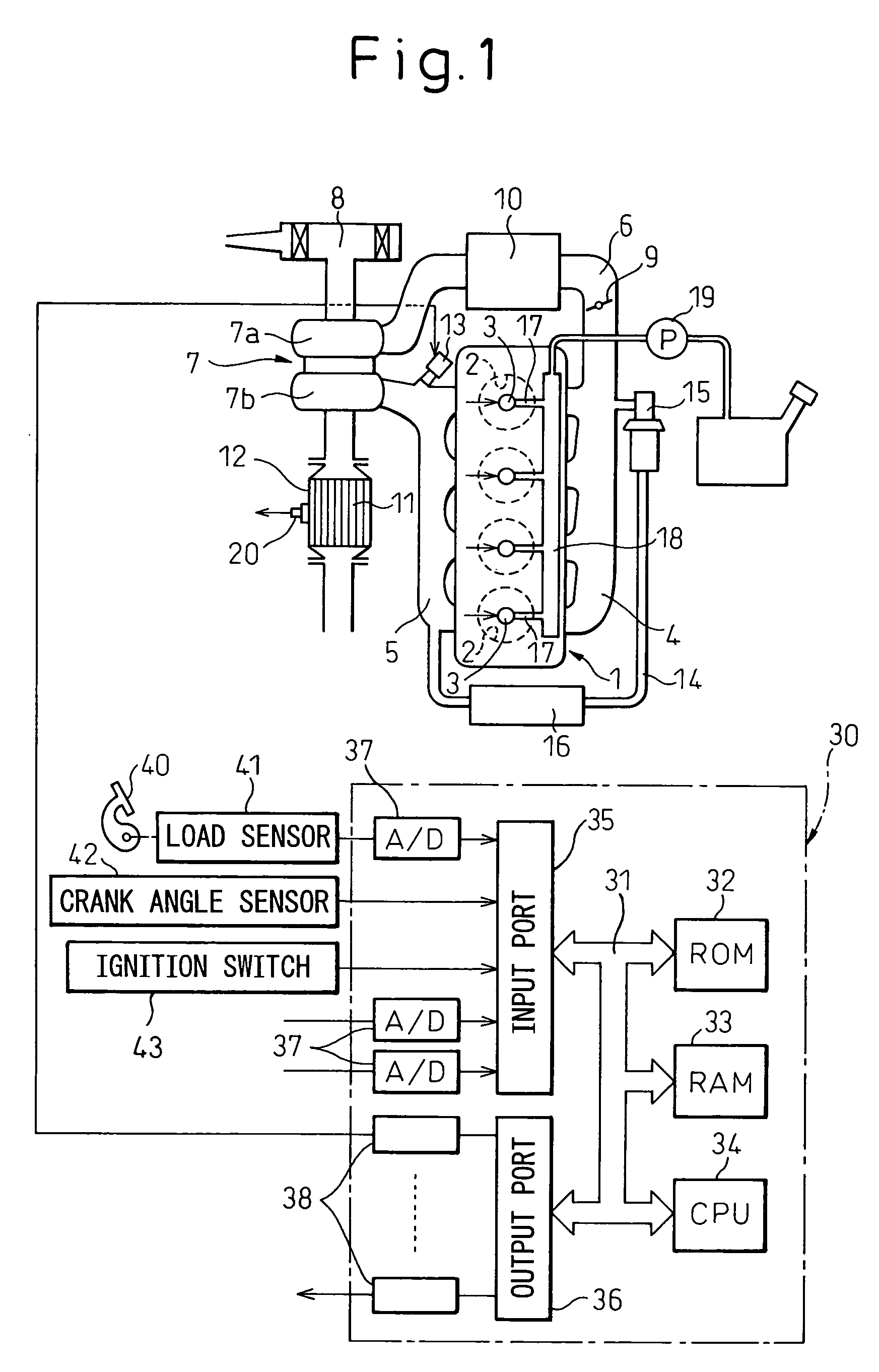
[0037]FIG. 1 shows the case of application of the present invention to a compression ignition type internal combustion engine. Note that the present invention may also be applied to a spark ignition type internal combustion engine.
[0038]Referring to FIG. 1, 1 indicates an engine body, 2 a combustion chamber of each cylinder, 3 an electronically controlled fuel injector for injecting fuel into each combustion chamber 2, 4 an intake manifold, and 5 an exhaust manifold. The intake manifold 4 is connected through an intake duct 6 to an outlet of a compressor 7a of an exhaust turbocharger 7. The inlet of the compressor 7a is connected to an air cleaner 8. Inside the intake duct 6 is arranged a throttle valve 9 driven by a step motor. Further, around the intake duct 6 is arranged a cooling device 10 for cooling the intake air flowing through the inside of the inta...
PUM
 Abstract
Description
Claims
Application Information
 - R&D
- Intellectual Property
- Life Sciences
- Materials
- Tech Scout
- Unparalleled Data Quality
- Higher Quality Content
- 60% Fewer Hallucinations
Browse by: Latest US Patents, China's latest patents, Technical Efficacy Thesaurus, Application Domain, Technology Topic, Popular Technical Reports.
© 2025 PatSnap. All rights reserved.Legal|Privacy policy|Modern Slavery Act Transparency Statement|Sitemap|About US| Contact US: help@patsnap.com


