Refrigerant cycle apparatus

a technology of refrigerant cycle and apparatus, which is applied in the direction of mechanical equipment, refrigeration components, lighting and heating equipment, etc., can solve the problems of increasing power consumption, and compressing liquid and affecting the efficiency of refrigeration equipmen

Active Publication Date: 2006-12-05
SANYO ELECTRIC CO LTD
View PDF10 Cites 2 Cited by
  • Summary
  • Abstract
  • Description
  • Claims
  • Application Information

AI Technical Summary

Benefits of technology

[0039]Especially, when the compressor includes first and second compression elements driven by a driving element, the refrigerant is sucked into the first compression element from the low-pressure side of the refrigerant circuit and compressed, and the refrigerant discharged from the first compression element and having an intermediate pressure is sucked into the second compression element, compressed, and discharged to a gas cooler, liquid return can effectively eliminated to prevent a liquid refrigerant from being sucked into the compressor at the starting time.

Problems solved by technology

There has been a possibility that the compressor compresses liquid and is damaged.
Especially, when the compressor is operated at a constant speed, the pressure on the high-pressure side further rises at the time of the starting of the compressor (pull-down time), exceeds a designed pressure of the apparatus, and has a possibility that the apparatus is damaged in a worst case.
On the other hand, when an inexpensive capillary tube is used in the throttling means, in addition to the above-described abnormal rise of the pressure on the high-pressure side, there has been a problem of an increase of power consumption, because the rotation number of the compressor needs to be raised in order to lower an evaporation temperature of the refrigerant in the evaporator.
In this relation, it has been difficult to obtain a desired cooling capability (refrigerating capability) in the evaporator.
Furthermore, in the refrigerant cycle apparatus using carbon dioxide described above, since the high-pressure side becomes supercritical, the pressure on the high-pressure side rises regardless of the outside air temperature, and exceeds the designed pressure of the apparatus, and the apparatus is possibly damaged in the worst case.
On the other hand, when the accumulator is disposed on a low-pressure side of the refrigerant cycle, a larger filling amount of refrigerant is required.
A problem has also occurred that an installation space is enlarged.

Method used


Image

  • Refrigerant cycle apparatus
  • Refrigerant cycle apparatus
  • Refrigerant cycle apparatus

Examples


Embodiment Construction

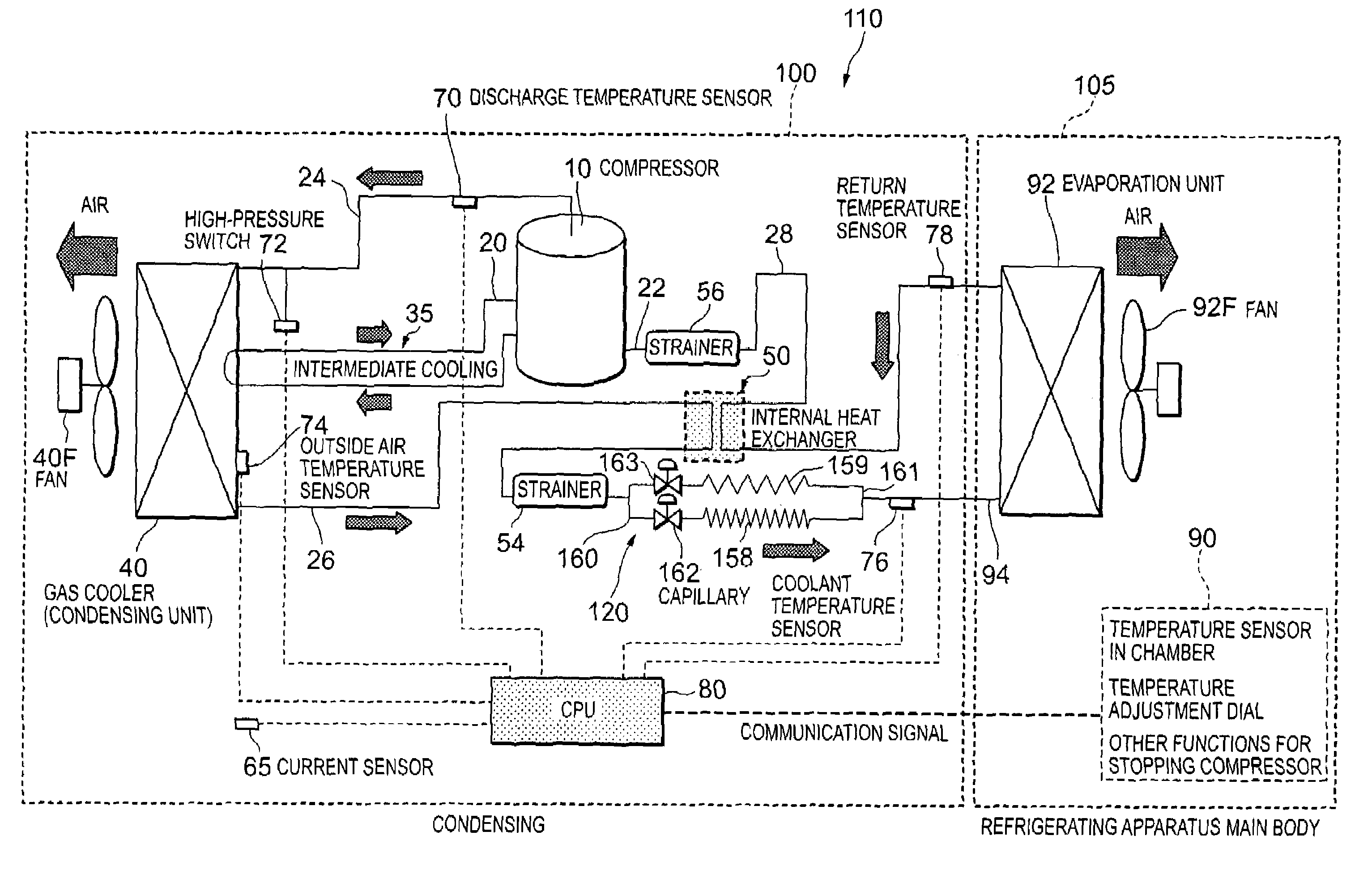
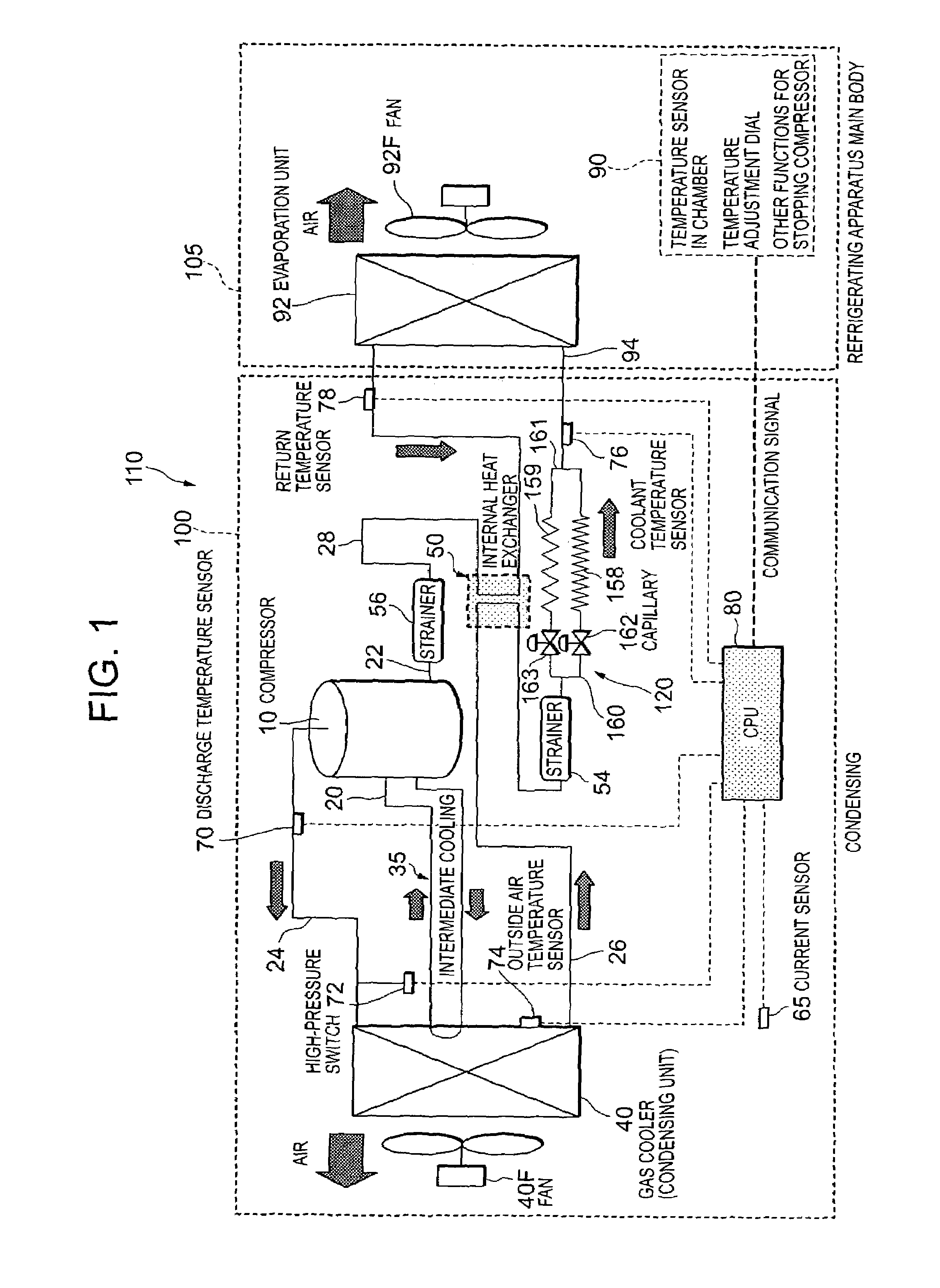
[0047]Next, embodiments of the present invention will be described in detail with reference to the accompanying drawings. FIG. 1 is a refrigerant circuit diagram of a refrigerant cycle apparatus 110 to which the present invention is applied. The refrigerant cycle apparatus 110 of the present embodiment is, for example, a showcase installed in a store. The refrigerant cycle apparatus 110 is constituted of a condensing unit 100 and a refrigerating apparatus main body 105 constituting a cooling apparatus main body. Therefore, the refrigerating apparatus main body 105 is a main body of the showcase.

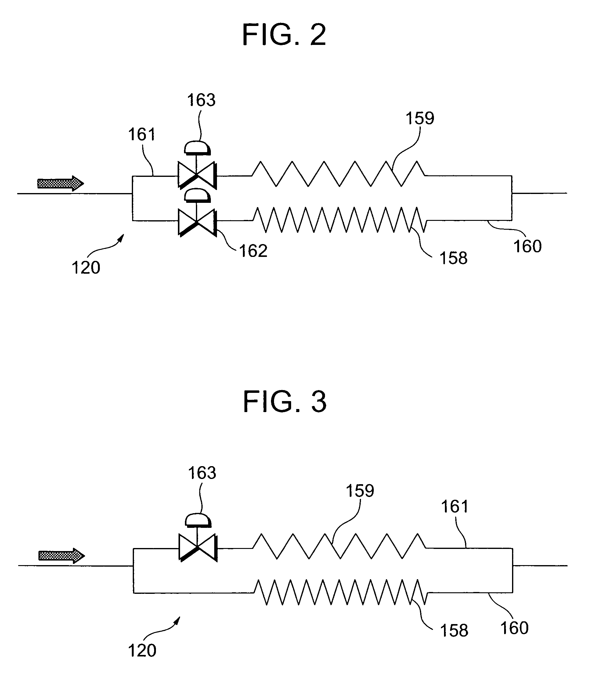
[0048]The condensing unit 100 includes a compressor 10, gas cooler (condenser) 40, and a throttling mechanism 120 described later as throttling means, and is connected to an evaporator 92 of the refrigerating apparatus main body 105 described later via a piping, and the compressor 10, gas cooler 40, and throttling mechanism 120 constitute a predetermined refrigerant circuit together with the ...


PUM


Abstract

There is disclosed a refrigerant cycle apparatus capable of avoiding occurrence of an abnormal rise in a pressure on a high-pressure side in advance, comprising: a throttling mechanism including a first capillary tube, and a second capillary tube which is connected in parallel to the first capillary tube and whose flow path resistance is smaller than that of the first capillary tube; and a valve device for controlling refrigerant circulation into the first and second capillary tubes, so that a refrigerant is passed into the second capillary tube at the time of starting of a compressor.

Description

BACKGROUND OF THE INVENTION[0001]The present invention relates to a refrigerant cycle apparatus constituted by successively connecting a compressor, a gas cooler, throttling means and an evaporator.[0002]In this type of conventional refrigerant cycle apparatus, a refrigerant cycle (refrigerant circuit) is constituted by successively piping and connecting a rotary compressor (compressor), a gas cooler, throttling means (expansion valve or the like), an evaporator and the like in an annular form. Further, a refrigerant gas is taken into a low-pressure chamber side of a cylinder from an intake port of a rotary compression element of the rotary compressor, and a refrigerant gas at a high temperature and a high pressure is obtained by compression performed by operations of a roller and a vane. This gas is then discharged to the gas cooler from a high-pressure chamber side through a discharge-port and a discharge sound absorbing chamber. The gas cooler releases heat from the refrigerant g...

Claims


Application Information

Patent Timeline
Patent Type & Authority Patents(United States)
IPC IPC(8): F25B41/00F25B41/04F25B49/00F25B1/00F25B1/10F25B9/00F25B40/00F25B41/06F25B49/02
CPCF25B1/10F25B41/067F25B49/022F25B9/008Y02B30/741F25B40/00F25B2309/061F25B2341/0661F25B2500/26F25B2500/28F25B2600/021F25B2600/2513F25B2700/15F25B2700/2104F25B2700/2106F25B2700/21152F25B2700/21174F25B2700/21175Y02B30/70F25B41/37F25B41/385F25B1/00
Inventor YAMASAKI, HARUHISAYAMANAKA, MASAJIMATSUMOTO, KENZOISHIGAKI, SHIGEYAFUJIWARA, KAZUAKIYUMOTO, TSUNEHISA
Owner SANYO ELECTRIC CO LTD
Why Eureka
Try Eureka