
Method and apparatus for supplying power in electronic equipment

Active Publication Date: 2006-11-21
ORACLE INT CORP
View PDF19 Cites 46 Cited by
  • Summary
  • Abstract
  • Description
  • Claims
  • Application Information

AI Technical Summary

Benefits of technology

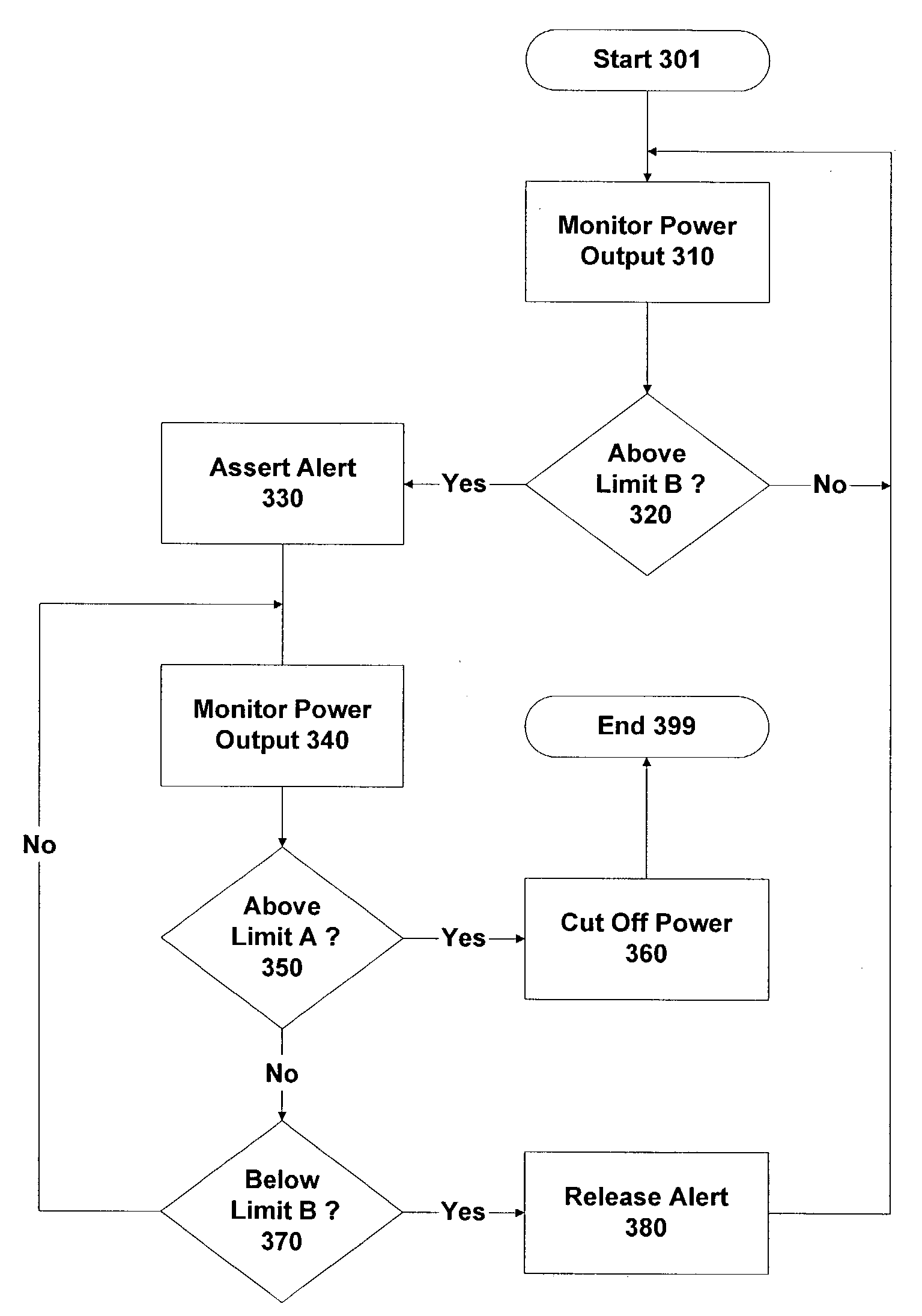
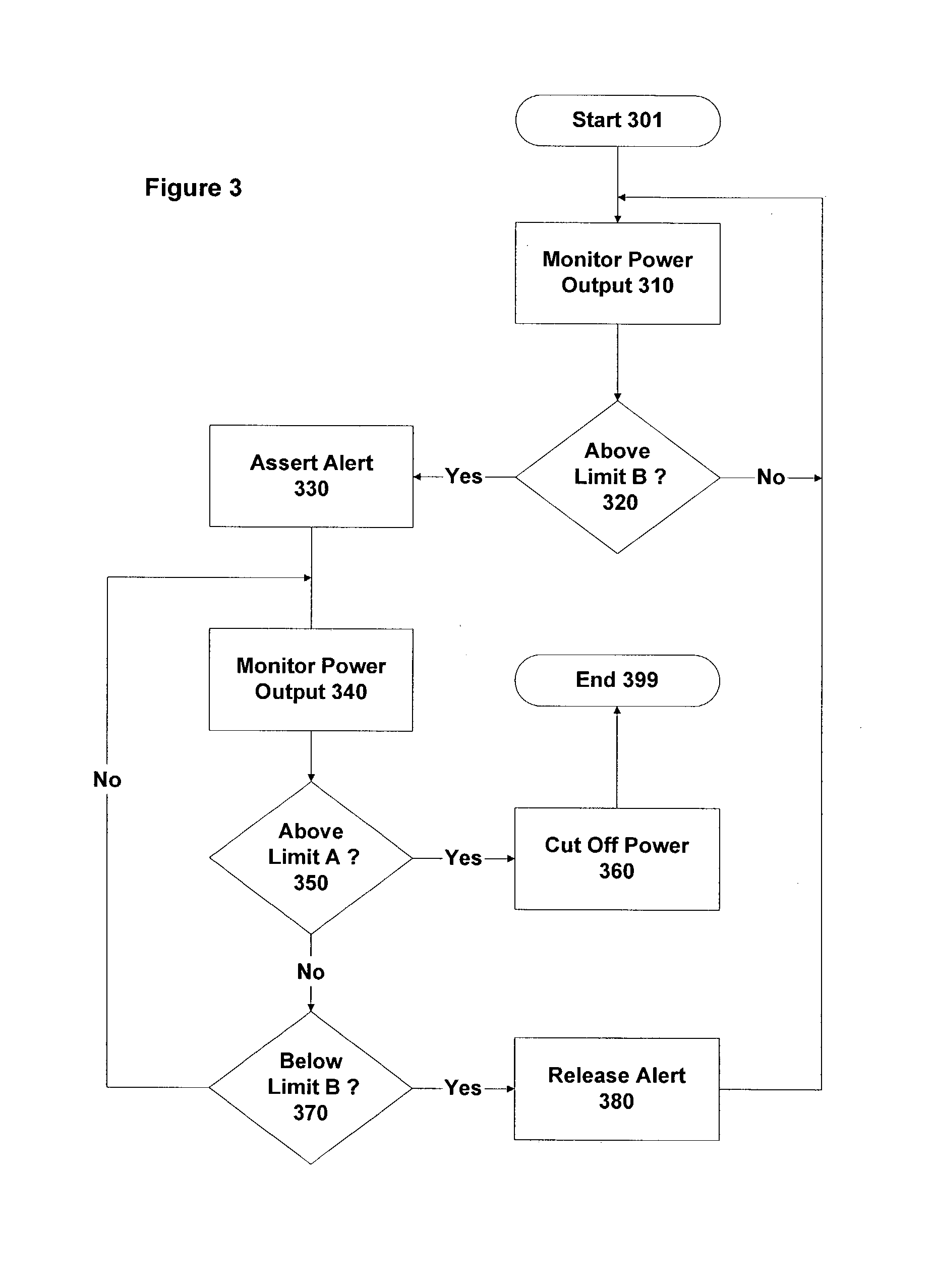
[0014]Thus in accordance with one embodiment of the invention, there is provided apparatus comprising one or more electronic components and a power supply unit to provide power to the electronic components. The power supply unit incorporates a detector to detect if the power output level from the power supply unit increases beyond a predetermined limit or threshold. If so, the power supply unit outputs an alert signal to the electronic component(s), which are responsive to this signal to reduce their power consumption. In this manner, the power supply unit can be protected against overload, particularly with respect to any sudden, short-term peaks in power consumption.
[0019]Note that the power supply unit typically also includes an automatic cut-out, which triggers to protect the power supply unit from damage caused by excess power drain. This automatic cut-out is set to occur at a power output level greater than the predetermined limit. More accurately (from a design perspective), the predetermined limit is normally specified at a value substantially below this cut-out point. Thus the automatic cut-out provides a fail-safe or back-up protection facility for the power supply unit. Nevertheless, by providing sufficient margin between the predetermined limit and the cut-out point, it is intended that the use of the alert signal allows those power consumption peaks that would otherwise trigger a cut-out to be smoothed, so that such a cut-out no longer occurs. It will be appreciated that this then allows the system to continue normal processing operations, without the need for a reboot and possible loss of user data.
[0031]In accordance with another embodiment of the invention, there is provided a computer system. The computer system comprises at least one digital electronic semiconductor component and a power supply unit operable to provide direct current (DC) power to the digital electronic semiconductor component. The power supply unit is responsive to its DC power output increasing beyond a predetermined limit to assert a control signal. This control signal is passed to the digital electronic semiconductor component, which is responsive to assertion of the control signal to reduce its power consumption.

Problems solved by technology

One problem in the design of power supplies for computers is that there can be significant fluctuations in the amount of power that such devices require.
This is particularly a problem in relation to digital electronic components.
As is well-known, data access to RAM is generally slow compared to the normal processing speed of the CPU, and so most systems are provided with one or more cache units (either inside or adjacent to the CPU).
This will generally cause the power consumption of the RAM to increase by approximately a corresponding factor of ten.
It will be appreciated that this adds considerably to the cost of the power supply.
Unfortunately, it is rather difficult to accurately predict or model the peak power usage of certain digital electronic devices.
Typically the power consumption of the FPU is highly dependent upon the data being processed, but this dependency is very complex and difficult to predict at design time.
Again, this over-specification increases costs for the power supply.
Nevertheless, it is difficult to be absolutely confident that the margins provided are indeed adequate, in which case the FPU or other device may be vulnerable to some obscure (pathological) data sequence that causes the power supply to be over-stressed.
Typically the power supply will then cut out as a safety precaution (rather than burning out), leading at least to the need for a system reboot, and the possible loss of data as well.
Note that if such a pathological data sequence does exist, but does not become known until after a system has shipped, then it is extremely difficult to protect against it in the field.
This is because the offending data sequence would generally appear as a set of standard data processing operations, and so would be very hard to detect specifically in either software or hardware.
Furthermore, even if the probability of such a data sequence being used by accident were extremely small, there is the risk that it may be used deliberately, such as by a hacker or terrorist, as part of a malicious attack on the system.
Furthermore, customers frequently perform upgrades to installed systems as well, such as by supplementing or replacing existing components with new and more powerful components that were not necessarily available when the system was originally designed and purchased.
It is difficult for a manufacturer to rigorously test every single potential configuration.
Nevertheless, there may be some subtle and unexpected differences in the way that slightly different versions of a component perform or interact with other components that do impact power consumption.
This in turn might adversely affect system operation and reliability for certain particular configurations.
In summary therefore, existing computer systems tend to have power supplies that are conservatively engineered, and so are rather expensive compared to the demand that is placed on them for normal system operations.
Even so, despite the significant safety margins provided, it is difficult to be absolutely certain that there is no pathological combination of operations or potential system reconfiguration that will not overload the power supply, and so lead to a system failure.

Method used


Image

  • Method and apparatus for supplying power in electronic equipment
  • Method and apparatus for supplying power in electronic equipment
  • Method and apparatus for supplying power in electronic equipment

Examples


Embodiment Construction

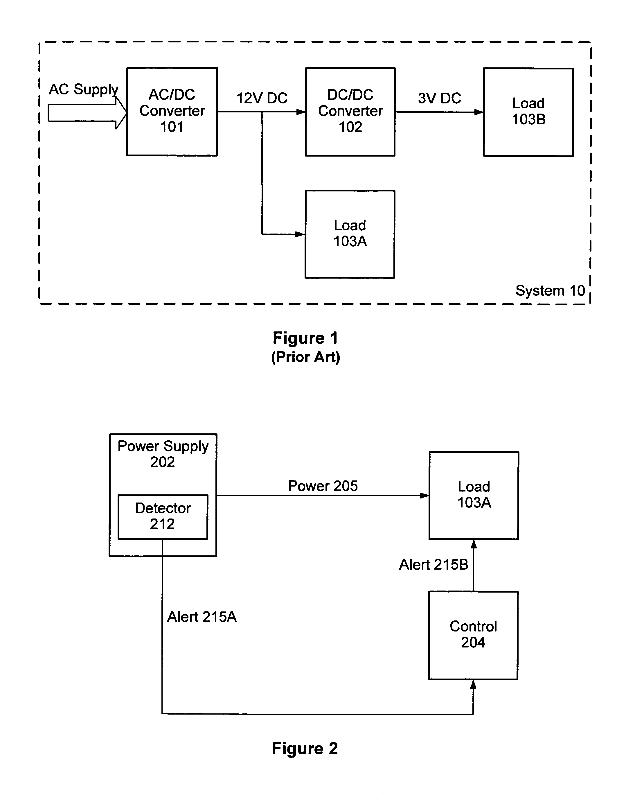
[0041]FIG. 2 is a schematic diagram of a power supply configuration in accordance with one embodiment of the present invention. Power supply 202 provides power 205 to load 103. Typically power supply 202 corresponds to DC / DC converter 102 in FIG. 1, but it can also correspond to AC / DC converter 101, or to any other appropriate power supply device.

[0042]Included within the power supply 202 is a detector 212 that monitors the power output 205 from the power supply 202 to load 103. Detector 212 triggers when the power output from supply 202 moves towards the top end of the design capabilities of power supply 202. Note that this trigger point is still short of the level at which power supply 202 may be damaged, and at which an automatic cut-out (not shown in FIG. 2) is typically implemented.

[0043]If the output from power supply 202 does go beyond this trigger point, then detector 212 asserts an alert signal 215A. This alert signal 215A is passed to control unit 204, which in turn forwar...


PUM


Abstract

A method and apparatus are disclosed for supplying power in electronic equipment. Thus the apparatus comprises at least one electronic component and a power supply unit that provides power to the electronic component. The power supply unit incorporates a detector that is responsive to the power output level from the power supply unit increasing beyond a predetermined limit. If this limit is breached, the power supply unit outputs a delay signal to the electronic component. This delay signal then causes the electronic component to reduce its power consumption (such as by performing dummy operations), thereby avoiding an overload on the power supply unit.

Description

FIELD OF THE INVENTION[0001]The present invention relates to power supplies in electronic equipment such as computers, and in particular to allowing such power supplies to better cope with variations in power demand.BACKGROUND OF THE INVENTION[0002]FIG. 1 provides a schematic representation of the power supply arrangement in a typical computing device 10. The system receives AC power supply from the mains or other appropriate source. The AC supply is fed into an AC / DC converter 101, which outputs a DC power supply at some intermediate voltage (e.g. 12 Volts). This output is then supplied directly to some of the components within system 10, as illustrated schematically by load 103A in FIG. 1. Typically load 103A comprises various electromechanical devices, such as disk drives, fans, and so on.[0003]System 10 further includes components, depicted schematically in FIG. 1 as load 103B, which require a lower DC voltage than load 103A. Accordingly, system 10 also incorporates a DC / DC conv...

Claims


Application Information

Patent Timeline
IPC IPC(8): G06F1/26G05F1/10G06F1/28G06F1/32
CPCG06F1/28G06F1/3203G06F1/3243Y02B60/1239Y02D10/00
Inventor WILLIAMS, EMRYS J.
Owner ORACLE INT CORP
Learn More