Eureka AIR delivers breakthrough ideas for toughest innovation challenges, trusted by R&D personnel around the world.

Method and apparatus for estimating the position of a terminal based on identification codes for transmission sources

a technology of identification codes and terminals, applied in the field of position determination, can solve the problems of insufficient power levels of signals from gps satellites to be received by the terminal, inaccurate position estimates based on these measurements, and general limited use of gps satellites for position determination, so as to achieve a minimal impact on performance

Inactive Publication Date: 2006-11-21
QUALCOMM INC
View PDF11 Cites 69 Cited by
  • Summary
  • Abstract
  • Description
  • Claims
  • Application Information

AI Technical Summary

Benefits of technology

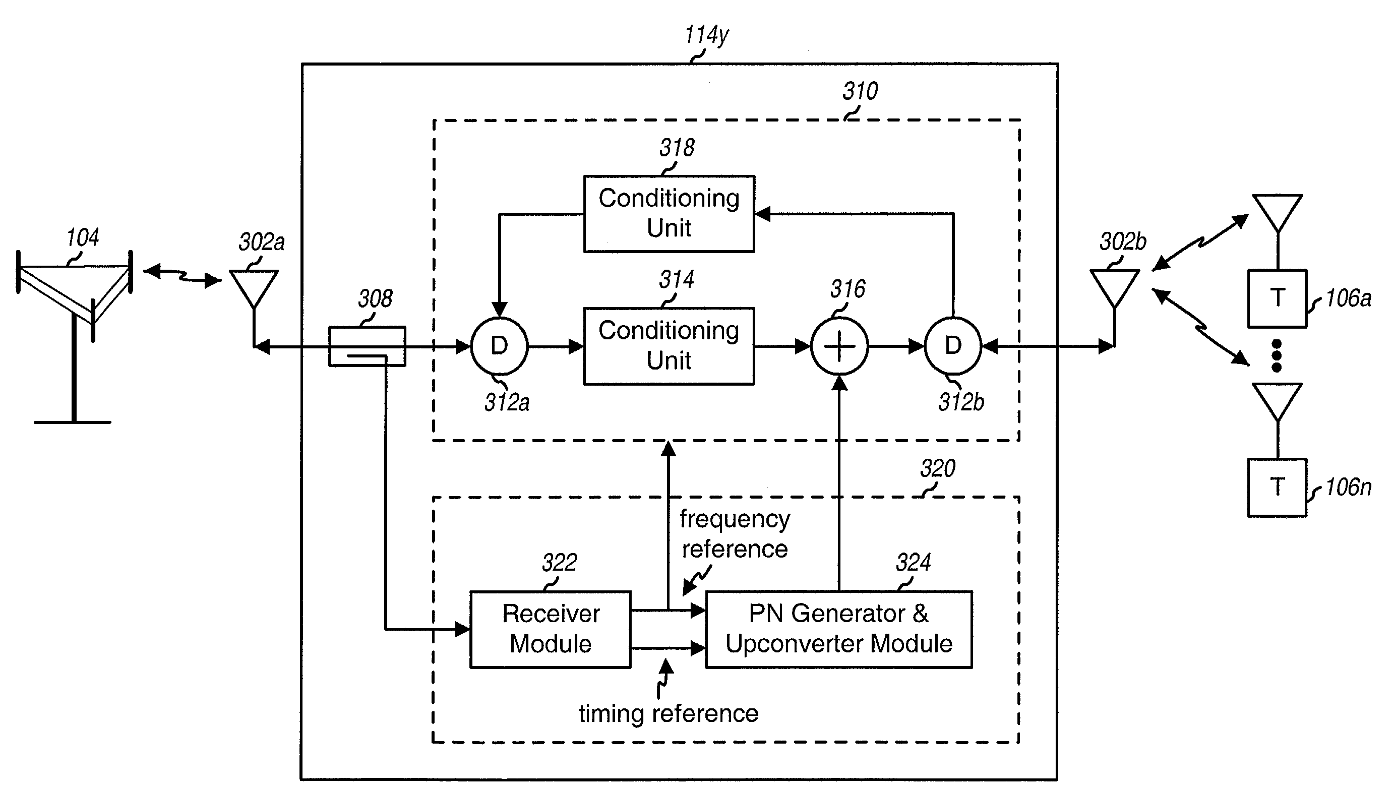
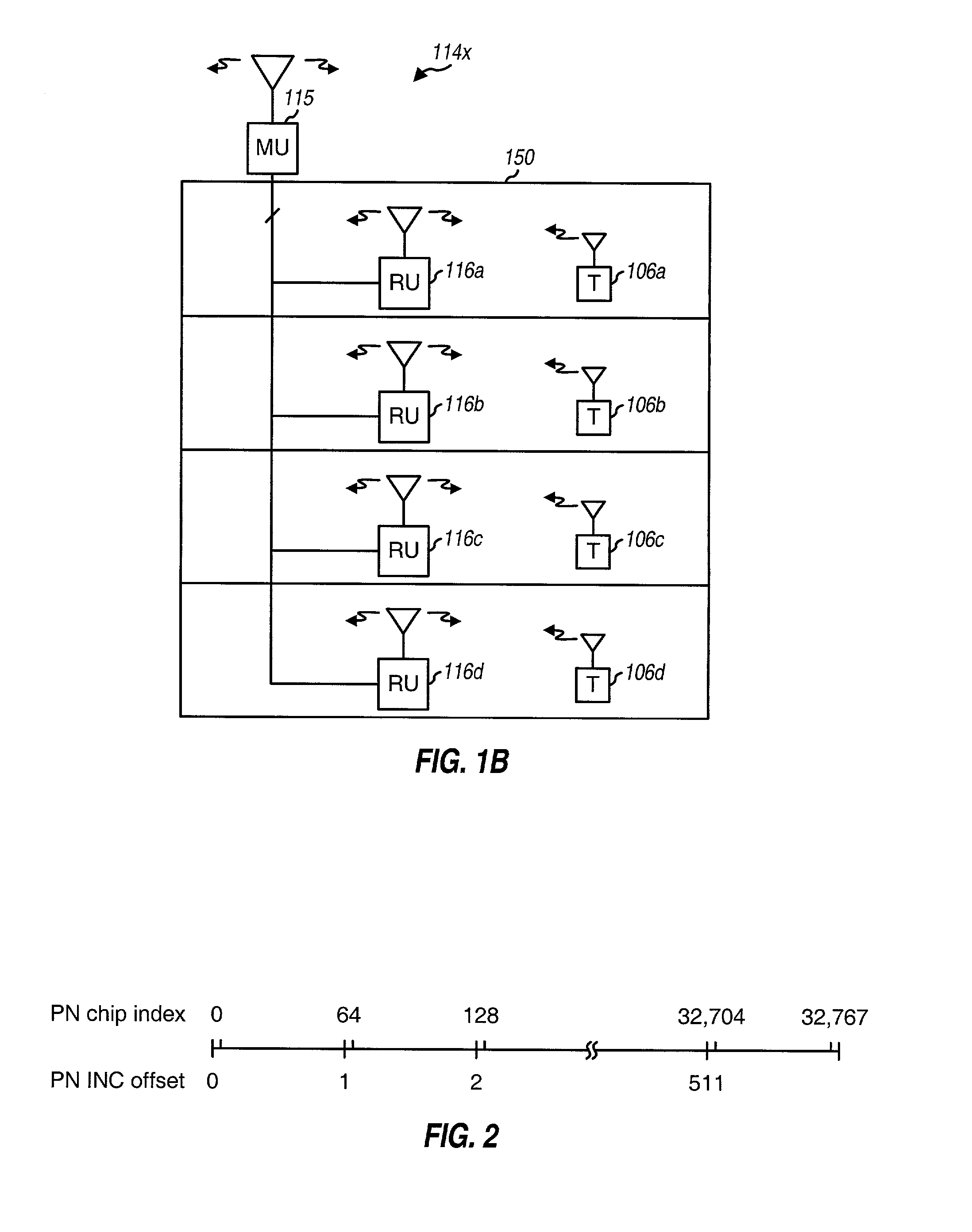
[0023]In another embodiment, the identification code for each repeater is transmitted using a spread-spectrum signal. This spread spectrum identifier signal can be designed to have minimal impact on the performance of the CDMA system and can be recovered in similar manner as a forward modulated signal transmitted from a base station or a repeater. In this way, no additional hardware is required for a terminal to recover the identifier signal. In an embodiment, the spread spectrum identifier signal is generated in accordance with and conforms to the IS-95 CDMA standard.
[0024]In yet another embodiment of the disclosed method and apparatus, when a signal is determined to have passed through a repeater, that signal is not used in position location calculations. This provides a simple and inexpensive way to ensure that the delay that is added to the signals travel time from the base station to the terminal does not cause an error in the position location calculations. That is, since the propagation delay between the time the signal is transmitted from the base station and the time the signal is received by the terminal will not accurately reflect the distance between the base station and the terminal, this delay should not be used in position location calculations. If additional information is available regarding the identity of the repeater that the signal passed through and the location of that repeater, then that information can be used in the calculation. However, it should be noted that there may be sufficient information from other signals that do not pass through repeaters to make it possible to calculate the position of the terminal without using information from signals that do pass through a repeater. In either case, it is important that the fact that the signal passed through a repeater be known so that the additional delay imparted on the signal by the repeater can be taken into account, either by not using timing information for that signal, or by adjusting that timing information appropriately.

Problems solved by technology

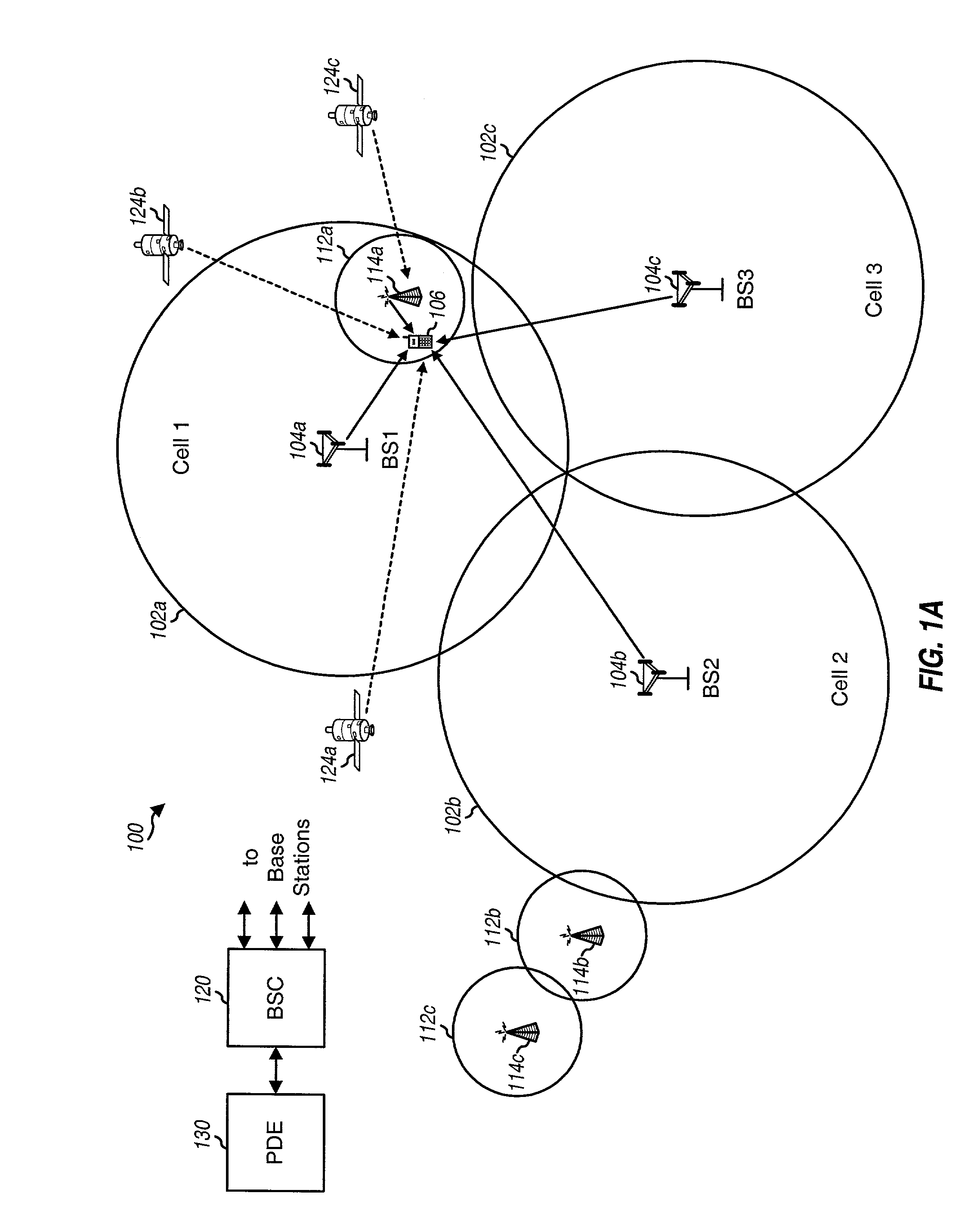
Various challenges are encountered in determining the location of a terminal in a system in which one or more repeaters are employed.
Moreover, in many cases in which repeaters are used (e.g., inside buildings, tunnels, subways, and so on), the signals from GPS satellites have insufficient power levels to be received by the terminal.
Furthermore, the additional delays introduced by repeaters can distort the round trip delay / time of arrival (RTD / TOA) measurements as well as the TDOA measurements, which then results in inaccurate position estimate based on these measurements.
Accordingly, the use of GPS satellites for position determination is generally limited to outdoor environment where obstructions are not present.
GPS signals typically cannot be received indoors or in other environments where there are obstructions such as foliage or buildings.
However, the measurements derived from base stations are typically less accurate than those from GPS satellites because multiple signals may be received at the terminal from a particular base station due to a phenomenon known as “multipath”.
However, this may not necessarily be true.
However, a repeater is associated with additional delays due to circuitry within the repeater and cabling and / or additional transmission associated with the repeater.
As an example, surface acoustic wave (SAW) filters, amplifiers, and other components within the repeater introduce additional delays that are comparable to, or may be even greater than, the transmission delays from the base station to the terminal.
If the repeater delays are not taken into account, then the time measurements of the signals from repeaters cannot be reliably used to determine the position of a terminal.
Various challenges are encountered in estimating the position of a terminal located within a building where a repeater may be employed to provide coverage.
First, in many indoor applications, the terminals are not able to receive signals from the base stations or GPS satellites, or may receive signals from fewer transmitters than required to perform trilateration.

Method used


Image

  • Method and apparatus for estimating the position of a terminal based on identification codes for transmission sources
  • Method and apparatus for estimating the position of a terminal based on identification codes for transmission sources
  • Method and apparatus for estimating the position of a terminal based on identification codes for transmission sources

Examples


Embodiment Construction

[0039]Aspects of the disclosed method and apparatus provide techniques to determine the position of a terminal under the coverage of a repeater in a wireless communication system. In one aspect, techniques are provided for each repeater to send an identification code that can be used by the terminal (or the PDE) to ascertain the repeater's identity. This information can then be used to estimate the position of the terminal, as described below.

[0040]It is recognized by the disclosed method and apparatus that repeaters used to provide indoor coverage are typically designed to cover relatively small geographical areas (e.g., a building, a floor of the building, and so on). In an embodiment, since the coverage area of a repeater is typically small, the position estimate for a terminal under the repeater's coverage can be reported as a designated location within this coverage area, which may be the center of the coverage area. In many (if not most) cases, this reported position estimate ...


PUM


Abstract

Techniques to determine the position of a terminal under the coverage of a repeater in a wireless communication system. In an aspect, an identification code is transmitted for each repeater and used by the terminal (or a PDE) to unambiguously identify the repeater. The identification codes for the repeaters in the system can be implemented with PN sequences at defined offsets that are specifically reserved for repeater identification. In another aspect, the identification code for each repeater is transmitted using a spread-spectrum signal designed to have minimal impact on the performance of the system and to be recoverable by the terminal in similar manner as for a forward modulated signal. In this way, no additional hardware is required for the terminal to recover the identifier signal. In one specific design, the spread spectrum identifier signal is generated in accordance with and conforms to the IS-95 CDMA standard.

Description

RELATED APPLICATIONS[0001]This application is a continuation in part of U.S. patent application Ser. No. 09 / 933,629, filed Aug. 20, 2001, now abandoned entitled “METHOD AND APPARATUS FOR ESTIMATING THE POSITION OF A TERMINAL BASED ON IDENTIFICATION CODES FOR TRANSMISSION SOURCES,” which is a continuation in part of U.S. patent application Ser. No. 09 / 904,330, filed Jul. 12, 2001, now abandoned entitled “METHOD AND APPARATUS FOR ESTIMATING THE POSITION OF A TERMINAL BASED ON IDENTIFICATION CODES FOR TRANSMISSION SOURCES”, all of which claims priority to U.S. Provisional Application No. 60 / 286,274, filed Apr. 24, 2001 and U.S. Provisional Application No. 60 / 299,315, filed Jun. 18, 2001.FIELD OF THE INVENTION[0002]The present invention relates generally to position determination and more specifically to techniques for providing an estimate of the location of a terminal in a wireless communication system based on identification codes assigned to transmission sources such as repeaters.BA...

Claims


Application Information

Patent Timeline
Patent Type & Authority Patents(United States)
IPC IPC(8): H04Q7/20H04Q1/00G01S19/11G01S19/46H04B7/26H04W64/00H04W88/08
CPCH04W64/00H04W88/085
Inventor STEIN, JEREMY M.WEISSMAN, HAIM
Owner QUALCOMM INC
Why Eureka
Eureka Blog
Learn More