Wireless device having a battery selectively activated

a wireless device and selective activation technology, applied in the direction of electrical switches, contact mechanisms, electrical equipment, etc., can solve the problems of consuming vain battery power, affecting the service life of wireless devices, and requiring a considerable long time after the wireless device, so as to prevent the battery power of wireless devices

Inactive Publication Date: 2006-11-21
DENSO CORP
View PDF14 Cites 9 Cited by
  • Summary
  • Abstract
  • Description
  • Claims
  • Application Information

AI Technical Summary

Benefits of technology

[0012]According to the present invention, the battery power of the wireless device is prevented from being consumed in vain in periods of transportation or storage. The battery can be activated or inactivated (power supply is turned on or off) by simply controlling the insertion depth of the operating member. Other objects and features of the present invention will become more readily apparent from a better understanding of the preferred embodiment described below with reference to the following drawings.

Problems solved by technology

The wireless device is always exposed to water splash, sunshine or other hazardous atmosphere.
A considerably long period of time is required after the wireless device is manufactured until it is actually used.
If the battery is continuously kept activated, battery power is consumed in vain.

Method used


Image

  • Wireless device having a battery selectively activated
  • Wireless device having a battery selectively activated
  • Wireless device having a battery selectively activated

Examples


Embodiment Construction

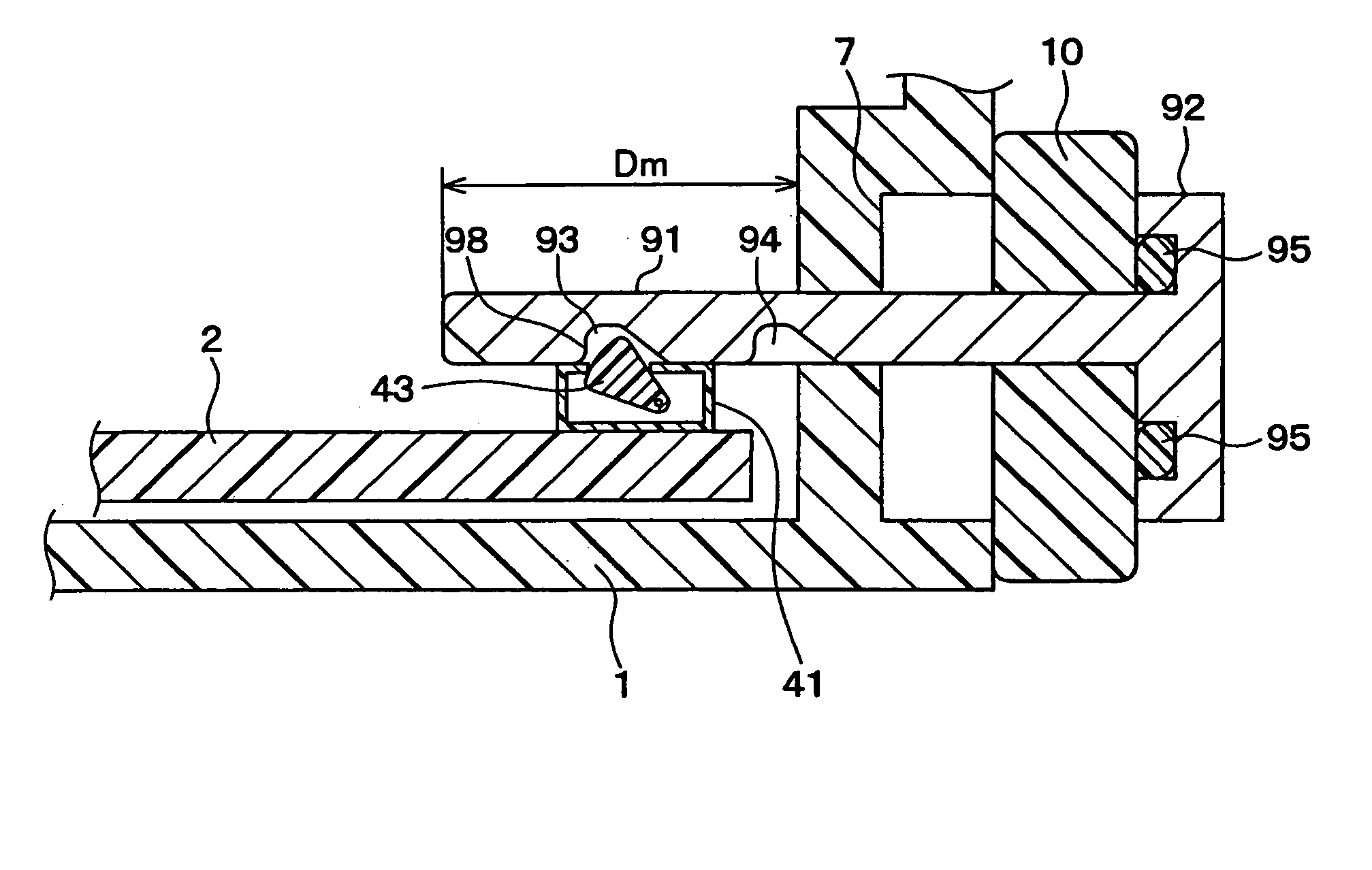
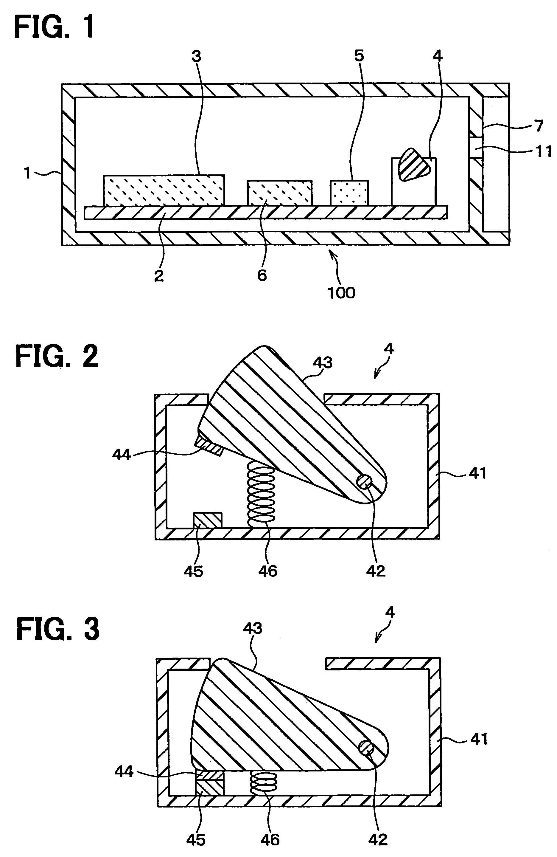
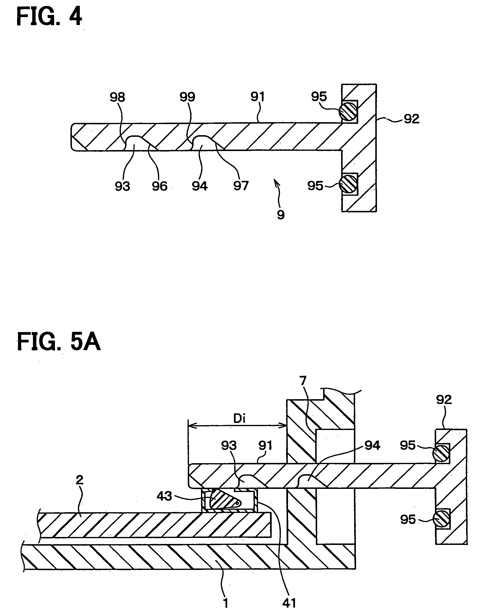
[0022]A first embodiment of the present invention will be described with reference to FIGS. 1–4. A wireless device 100 is mounted on a license plate of an automobile or installed in the vicinity of the license plate. The wireless device 100 is shaped in a rectangular box (e.g., 40 mm×40 mm×15 mm). FIG. 1 shows a cross-sectional view, assuming that the left side in FIG. 1 is the front side of the wireless device 100. The wireless device 100 wirelessly transmits information such as a license number and a vehicle identification number to a roadside device.

[0023]Components of the wireless device 100 are contained in a casing 1. A wireless circuit 3, a memory 6, a battery 5 and a switch 4 mounted on a substrate 2 are all contained in the casing 1. The casing 1 is made of a resin or metallic material. At the rear end of the casing 1, a hole 11 (e.g., 2 mm square) and a depressed portion 7 surrounding the hole 11 are formed. The depressed portion 7 is cylinder-shaped (viewed from the rear ...


PUM


Abstract

A wireless device to be mounted on a license plate of an automobile is composed of a casing, components contained in the casing and an operating member inserted into the casing. A battery for supplying power to the components is selectively turned on or off by controlling an insertion depth of the operating member into the casing. At an initial depth, the power supply is turned on for testing the wireless device at a manufacturing plant. At an intermediate depth, the power supply is turned off to save energy consumption in periods of transportation or storage. At a final depth, the power supply is finally turned on for actual use of the wireless device, and the casing is hermetically closed by the operating member.

Description

CROSS-REFERENCE TO RELATED APPLICATION[0001]This application is based upon and claims benefit of priority of Japanese Patent Application No. 2004-294738 filed on Oct. 7, 2004, the content of which is incorporated herein by reference.BACKGROUND OF THE INVENTION[0002]1. Field of the Invention[0003]The present invention relates to a wireless transmitter-receiver device in which electric power is selectively supplied from a battery to wireless circuits.[0004]2. Description of Related Art[0005]Recently, an automobile license plate on which a wireless device is mounted for wirelessly transmitting a license number and a vehicle identification number (a so-called smart plate) has been proposed. The wireless device is always exposed to water splash, sunshine or other hazardous atmosphere. Therefore, the wireless device including a battery for supplying power to wireless circuits has to be contained in a hermetically encapsulated casing. When the battery is contained in such a casing, it is i...

Claims


Application Information

Patent Timeline
Patent Type & Authority Patents(United States)
IPC IPC(8): H01H27/00
CPCH01H15/102H01H27/00H01H2003/0273
Inventor TANAKA, YUKIOMIYOSHIDA, SHINGO
Owner DENSO CORP
Why Eureka
Try Eureka