
Coaxial spray nozzle injector

a spray nozzle and injector technology, applied in the direction of liquid spraying apparatus, burners, jet propulsion plants, etc., can solve the problems of reducing the coefficient of propellant combustion efficiency, reducing the thrust specific impulse value, and affecting the effect of thrust, so as to increase the propellant contact area, increase the propellant combustion efficiency, and increase the effect of propellant contact area

Inactive Publication Date: 2006-11-21
FEDERAL STATE UNITARY ENTERPRISE CHEM AUTOMATIC DESIGN BUREAU CADB +1
View PDF15 Cites 10 Cited by
  • Summary
  • Abstract
  • Description
  • Claims
  • Application Information

AI Technical Summary

Benefits of technology

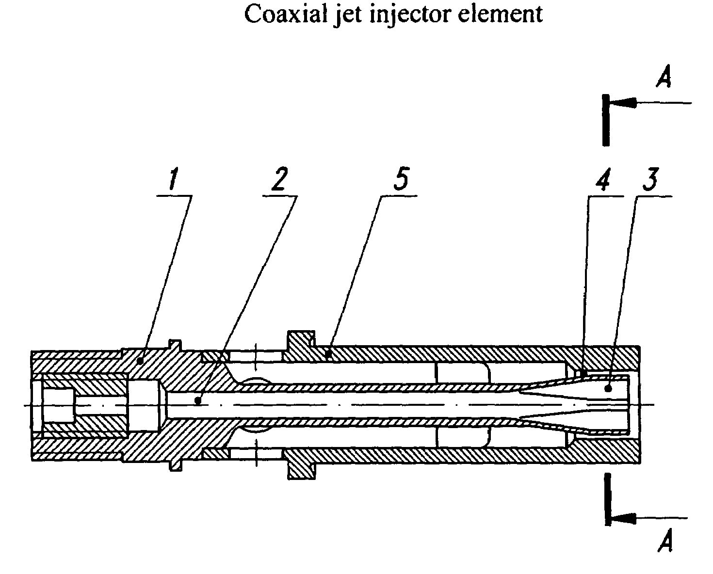
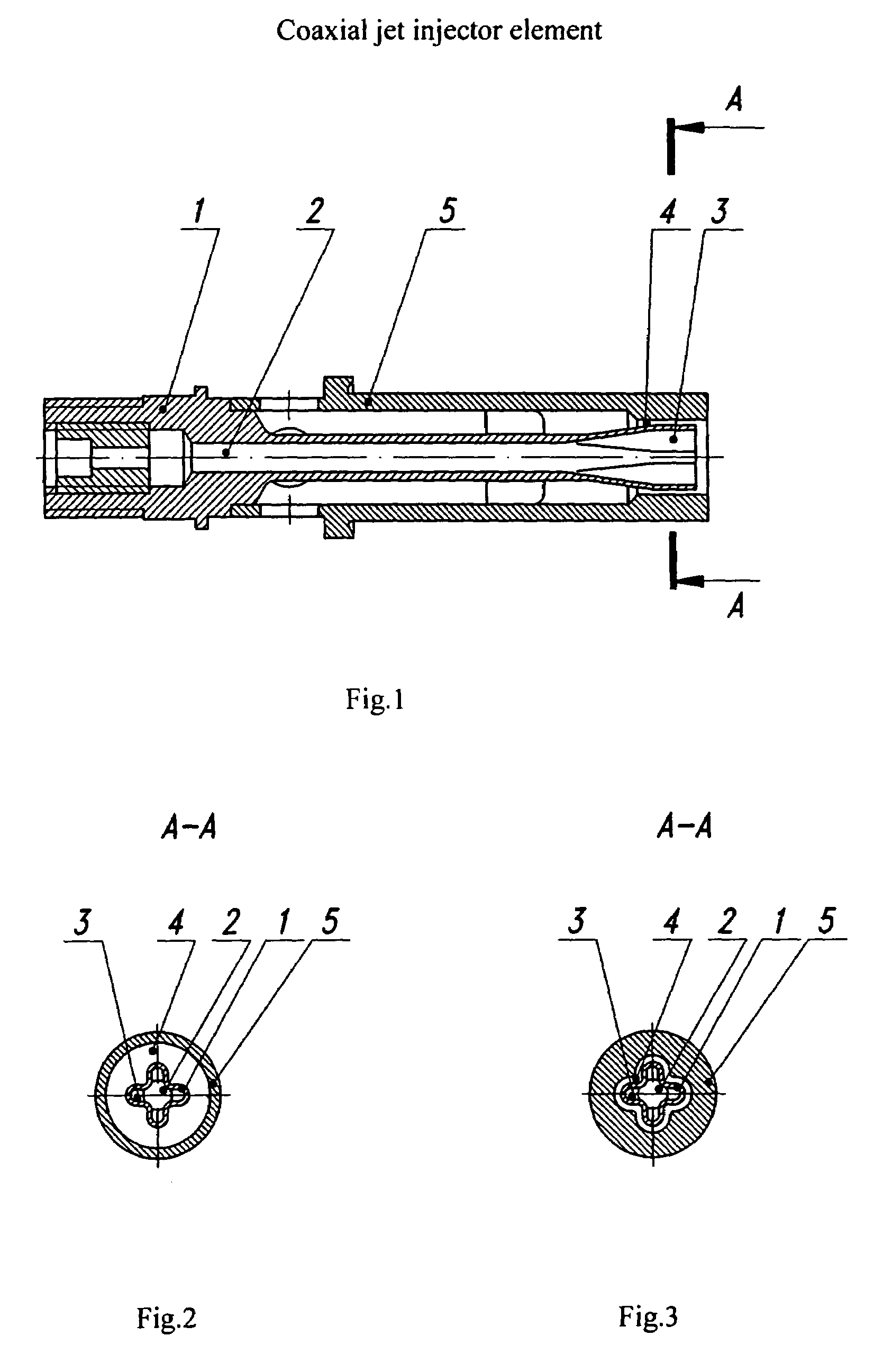
[0013]The invention task is to increase the propellant combustion efficiency through increasing of a propellant contact area at the cost of radial grooves provided on the tip outlet section. The provision of the grooves will allow to change the jet form of one of the propellants transforming the round jet into the star-shaped cross-section jet having several radial plums with unchanged tip cross-section area. This will increase the propellant contact area at the expense of additional contact on the plum surface and will decrease the characteristic cross-section size of jet of one of propellants thus increasing the combustion efficiency. The invention task is achieved by provision of radial grooves in the outlet portion of a tip pertained to the coaxial-jet injection element comprised of said hollow tip connecting the cavity of one propellant with the combustion zone, moreover, the said injection element is provided with a sleeve surrounding the said tip with provision of a clearance between them, the said clearance connects the cavity of another propellant with the combustion zone, being the said sleeve internal surface equidistant to the profiled external surface of tip grooves.
[0017]However, for the expander-cycle engines (liquid oxidizer, for example, oxygen and gaseous fuel, for example, hydrogen, are supplied into injection elements), it is true the following expression Fr=(0,6-1,0)F0. The comparative analysis shows that the open flow area for gaseous component in this case is ≈50% reduced. The use of the injection elements with the ratio Fr=(1,2-2,2)F0 in the expander-cycle engine reduces the gas flow rate by 50% leading to decrease of the propellant combustion efficiency. This has been proved in the hot tests of injection elements with such design when tested as integrated into the model LOX-LH2 expander cycle combustion chamber. The combustion efficiency in these tests was φK=0.9902 (instead of φK=0.994).

Problems solved by technology

One of the main problems in the development of devices for mixing and atomization propellants is to provide maximum attainable propellant combustion efficiency—this may be achieved through increase of an area of propellant contact surface and decrease of jet characteristic cross-section size for one of propellants.
Concerning known injector element designs, the realization of the above requirements leads to considerably complicated design.
Such supply scheme doesn't provide due quality of propellants spraying—this lowers the coefficient of propellant combustion efficiency and, as a consequence, leads to losses of the thrust specific impulse value.
The main disadvantage of the above mentioned devices is the low value of mixture formation completeness.
This leads to incomplete combustion of propellants and reduced efficiency.

Method used


Image

  • Coaxial spray nozzle injector
  • Coaxial spray nozzle injector

Examples


Embodiment Construction

[0026]As can be seen from the FIG. 1, the coaxial-jet injection element contains a hollow tip 1 having an axial channel 2 inside, the said channel connecting the oxidizer cavity with the combustion chamber internal cavity. The tip outlet portion has radial grooves 3. The sleeve 5 is mounted on the tip 1 providing the annular gap 4 and connecting the fuel cavity with the combustion chamber interior. In the first design option, the sleeve 5 inner surface is cylindrical (FIG. 2). In the second design option (FIG. 3), the sleeve inner surface is equidistant with the outer surface of tip grooves and the exit cross-section area of the clearance between the sleeve ribs and the tip grooves is Fr=(0,6-2,2)Fo, where Fo is the cross section area of the tip outlet.

[0027]The proposed injection element is functioning as follows.

[0028]The oxidizer from the oxidizer cavity is supplied into the combustion chamber through the channel 2 inside the tip 1. At the place of location of radial grooves 3, t...


PUM


Abstract

The invention relates to power plants, in particular to devices for mixing and atomizing propellant components, and may be used for development injection elements and injector heads of liquid-fuel rocket engines (LRE).The task of the invention is to increase the propellant component combustion efficiency via the increase of propellant component contact area.This task is solved by provision of radial grooves 3 in the outlet portion of a hollow tip 1 of the coaxial-jet injection element, the said hollow tip connecting the cavity of one propellant with the combustion zone, a sleeve 5 surrounding the said tip providing an annular gap 4 connecting the cavity of another propellant with the combustion zone. The sleeve inner surface outlet portion is equidistant relatively to the tip grooves outer surface, and the outlet cross-section area between the sleeve equidistant surface and the tip grooves is Fr=(0,6-2,2)Fo, where Fo is the groove cross-section area at the tip outlet, 2 dependent claims, 3 Figures.

Description

[0001]This application claims the benefit of PCT / RU00 / 00275 filed Jul. 5, 2000.FIELD OF THE INVENTION[0002]The invention relates to power plants, in particular to devices for mixing and atomizing propellant components, and may be used for development injection elements and injector heads of liquid-fuel rocket engines (LRE).BACKGROUND OF THE INVENTION[0003]One of the main problems in the development of devices for mixing and atomization propellants is to provide maximum attainable propellant combustion efficiency—this may be achieved through increase of an area of propellant contact surface and decrease of jet characteristic cross-section size for one of propellants.[0004]Concerning known injector element designs, the realization of the above requirements leads to considerably complicated design.[0005]It is known a coaxial jet injection element having a tip made as a hollow cylinder connecting the liquid oxidizer cavity with combustion zone (combustion chamber interior) and moreover,...

Claims


Application Information

Patent Timeline
Patent Type & Authority Patents(United States)
IPC IPC(8): F02C1/00B05B7/06F02K9/52F23D11/10F23D11/12F23D11/38
CPCF02K9/52F23D11/106F23D11/12
Inventor DMITRIEVICH, GOROKHOV VICTORDMITRIEVICH, LOBOV SERGEYVICTOROVICH, CHERNICHENKO VLADIMIR
Owner FEDERAL STATE UNITARY ENTERPRISE CHEM AUTOMATIC DESIGN BUREAU CADB
Learn More