Eureka AIR delivers breakthrough ideas for toughest innovation challenges, trusted by R&D personnel around the world.

Process for separating carbon dioxide from an oxygenate-to-olefin effluent stream

a technology of oxygenate and effluent, which is applied in the direction of extraction purification/separation, separation process, hydrocarbon oil treatment product, etc., can solve the problem of unreacted methanol likely to be present in the effluent, and achieve the effect of reducing the alkalinity and reducing the amount of carbon dioxid

Inactive Publication Date: 2006-11-14
EXXONMOBIL CHEM PAT INC
View PDF20 Cites 54 Cited by
  • Summary
  • Abstract
  • Description
  • Claims
  • Application Information

AI Technical Summary

Benefits of technology

[0012]The present invention is a process for removal of carbon dioxide from a reactor effluent stream comprising water, carbon dioxide and olefin(s) water is removed in a quenching step. Then, carbon dioxide is removed by contacting the quenched effluent stream with an alkaline stream, such as for example in an alkaline wash tower. The process conserves alkaline and accomplishes removal of carbon dioxide more efficiently.

Problems solved by technology

Furthermore, depending upon operating conditions, unreacted methanol is likely to be present in the effluent of the oxygenate-to-olefin reaction.

Method used


Image

  • Process for separating carbon dioxide from an oxygenate-to-olefin effluent stream
  • Process for separating carbon dioxide from an oxygenate-to-olefin effluent stream
  • Process for separating carbon dioxide from an oxygenate-to-olefin effluent stream

Examples


example 1

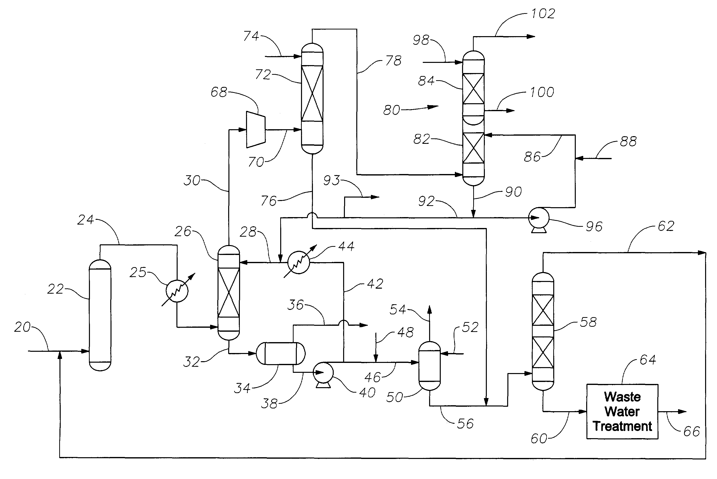
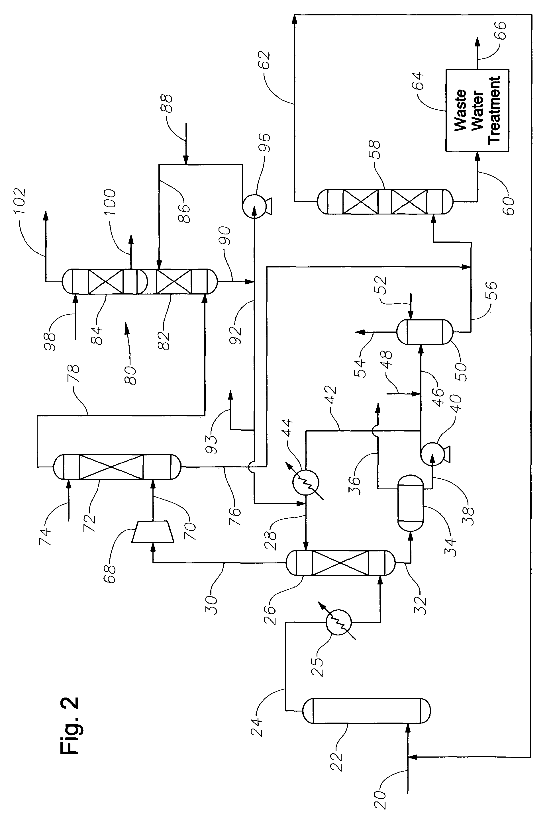
[0137]The flow diagram illustrated in FIG. 2 is used in Example 1. Effluent from the oxygenate to olefin reactor 22 passes through quench device 26 which removes water in the effluent stream (including the reactor effluent stream and the cooled effluent stream) and produces a quenched effluent stream. The quench medium is supplied along line 28. The pH of the quench medium is adjusted by adding alkaline from line 92 to line 28. According to this example, the alkaline is sodium hydroxide (NaOH). A portion of the carbon dioxide is removed in the quench device 26. The quenched effluent stream leaves the quench device 26 and directly or indirectly passes through an alkaline wash tower 80. The remainder of the carbon dioxide is removed from the quenched effluent stream in the alkaline wash tower 80. A portion of the bottoms stream 90 of the alkaline wash tower 80 is transported along line 92 to adjust the pH of the quench medium.

[0138]According to this example, a reactor effluent stream ...

example 2

[0143]The process of example 1 was followed in example 2 except that the pH of the quench medium was adjusted to 7. All acetic acid is removed and no carbon dioxide is removed in the quench device 26. All of the carbon dioxide is removed in the alkaline wash tower 80. The conditions for operating the quench device 26 and the alkaline wash tower 80 are shown in Table 2.

[0144]

TABLE 2Conditions of Quench DeviceAnd Alkaline Wash Tower in Example 2Alkaline WashQuench Device / QuenchTower / AlkalineConditionMediumWash MediumPressure2.72 atm18 atmTemperature of100° F.110° F.MediumpH of Medium7.014NaOH used per hour113 lbs / hr1828 lbs / hrNaOH used per0.42 kTa6.77 kTaprocessing 1000 kTa ofethylene and 1000 kTaof propylene

[0145]Under the foregoing conditions, a total of 1941 lbs / hr are used in the quench device 26 and alkaline wash tower 80. The process described in Example 2 uses 7.19 kTa of NaOH to process 1000 kTa of ethylene and 1000 kTa of propylene. A comparison of example 1 and example 2 ill...


PUM

PropertyMeasurementUnit
Fractionaaaaaaaaaa
Weightaaaaaaaaaa
Concentrationaaaaaaaaaa

Abstract

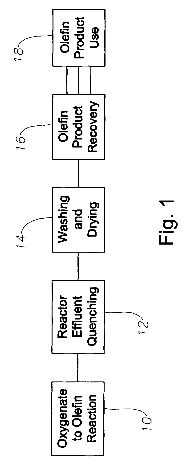
The present invention is a process for removal of carbon dioxide from a reactor effluent stream comprising water, carbon dioxide and olefin(s), where a portion of the carbon dioxide is removed in a quenching step with a quench medium and more carbon dioxide is removed by contacting the quenched effluent stream with an alkaline stream. A portion of the alkaline stream is added to the quench medium.

Description

FIELD OF THE INVENTION[0001]The present invention relates to a process for separating oxygenates from an oxygenate-to-olefin effluent stream.BACKGROUND OF THE INVENTION[0002]Olefin(s) are traditionally produced from petroleum feedstock by catalytic or steam cracking processes. These cracking processes, especially steam cracking, produce light olefin(s) such as ethylene and / or propylene from a variety of hydrocarbon feedstock. Ethylene and propylene are important commodity petrochemicals useful in many processes for making plastics and other chemical compounds. Ethylene is used to make various polyethylene plastics, and in making other chemicals such as vinyl chloride, ethylene oxide, ethylbenzene and alcohol. Propylene is used to make various polypropylene plastics, and in making other chemicals such as acrylonitrile and propylene oxide.[0003]The petrochemical industry has known for some time that oxygenates, especially alcohols, are convertible into light olefin(s). This process is...

Claims


Application Information

Patent Timeline
IPC IPC(8): C07C1/00C07C7/00C07C1/20C10G3/00
CPCC07C1/20C07C11/02C10G3/49B01D53/265B01D53/62B01D53/75C10G2400/20B01D53/1475B01D2251/304B01D2251/306B01D2252/204B01D2256/24B01D2257/504B01D2257/80Y02C10/04Y02P30/20Y02P30/40Y02C20/40Y02P20/151
Inventor DING, ZHONG YILATTNER, JAMES RICHARDSONLUMGAIR, JR., DAVID RITCHIEKABIN, JEFFREY ALAN
Owner EXXONMOBIL CHEM PAT INC
Why Eureka
Eureka Blog
Learn More