Hydraulic system for synchronized extension of multiple cylinders

a technology of synchronized extension and hydraulic system, which is applied in the direction of fluid coupling, servomotor, coupling, etc., can solve the problems of system failure, system failure, and loss of gear units around the sides of gears and through gear tooth surfaces, etc., and achieve the effect of lowering the support surfa

Active Publication Date: 2006-11-14
J R AUTOMATION TECH
View PDF30 Cites 3 Cited by
  • Summary
  • Abstract
  • Description
  • Claims
  • Application Information

AI Technical Summary

Benefits of technology

[0009]Another aspect of the present invention includes a method comprising steps of providing at least two lift cylinder assemblies adapted for connection to a support surface for lifting and lowering the support surface. The method also provides a synchronizer having at least two isolated chambers corresponding to the at least two lift cylinder assemblies, a rod extending axially through the chambers, and pistons mounted on the rod and located in the isolated chambers. The method also provides a hydraulic pump; and a hydraulic circuit operably connecting the pump to the synchronizer and to the at least two lift cylinder assemblies for controlling and providing synchronized movement of the at least two lift cylinder assemblies, the hydraulic circuit including hydraulic fluid and including a valving arrangement. The method includes operating the valving arrangement to automatically purge air entrapped in the hydraulic fluid without disconnection of any hydraulic lines and without evacuation or bleeding of the hydraulic lines.
[0010]Another aspect of the present invention includes a method comprising steps of providing at least two lift cylinder assemblies adapted for connection to a support surface for lifting and lowering the support surface. The method also provides a synchronizer having at least two isolated chambers corresponding to the at least two lift cylinder assemblies, a rod extending axially through the chambers, and pistons mounted on the rod and located in the isolated chambers. The method further provides a hydraulic pump and a hydraulic circuit operably connecting the pump to the synchronizer and to the at least two lift cylinder assemblies for controlling and providing synchronized movement of the at least two lift cylinder assemblies. A valving arrangement is provided that is operably connected to the hydraulic circuit. The method includes actuating the valving arrangement to automatically resynchronize positions of the at least two lift cylinder assemblies to each other and to the synchronizer without disconnection of any hydraulic lines and without evacuation or bleeding of the hydraulic lines.

Problems solved by technology

None of these systems are completely successful because loss of oil in the various devices accumulate and adversely affect synchronization.
For example, the gear units have losses around the sides of the gears and through the gear tooth surfaces.
The systems using proportioning valves also experience oil loss because of the clearance between the valve body and the spool.
Oil leaks and entrapped air and non-uniform loading also adversely affect synchronization and cause dissimilar extension of cylinders.
The loss of oil in any individual cylinder circuit especially hinders the functionality of the multi-cylinder system to move or lift objects in the intended even manner.
Over time, the higher leakage in one of the cylinder systems will cause the lifting cylinders to go out of phase and subsequently cause the system to fail.
Also, many synchronized hydraulic systems that use multiple cylinders in parallel will bind and cause stress concentrations leading to premature wear and increased maintenance.
Resynchronization and line-purging to eliminate trapped air in known synchronized hydraulic systems is undesirably time-consuming and labor-intensive, and is difficult to accomplish without messy maintenance procedures such as disconnecting, bleeding, and reconnecting hydraulic lines.
Further, repeated disconnections and re-connections undesirably increase the risk of new leaks.

Method used


Image

  • Hydraulic system for synchronized extension of multiple cylinders
  • Hydraulic system for synchronized extension of multiple cylinders
  • Hydraulic system for synchronized extension of multiple cylinders

Examples


Embodiment Construction

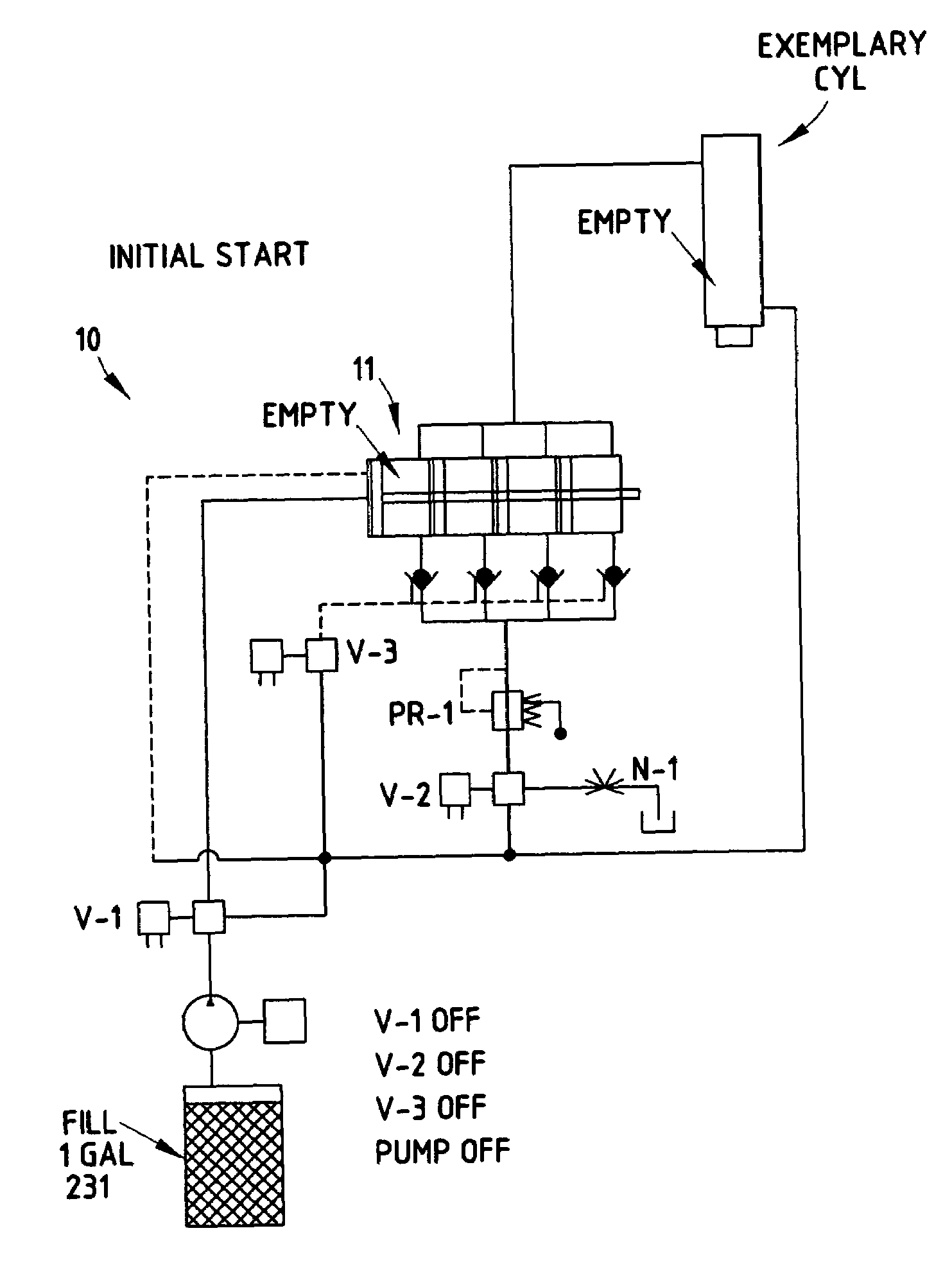
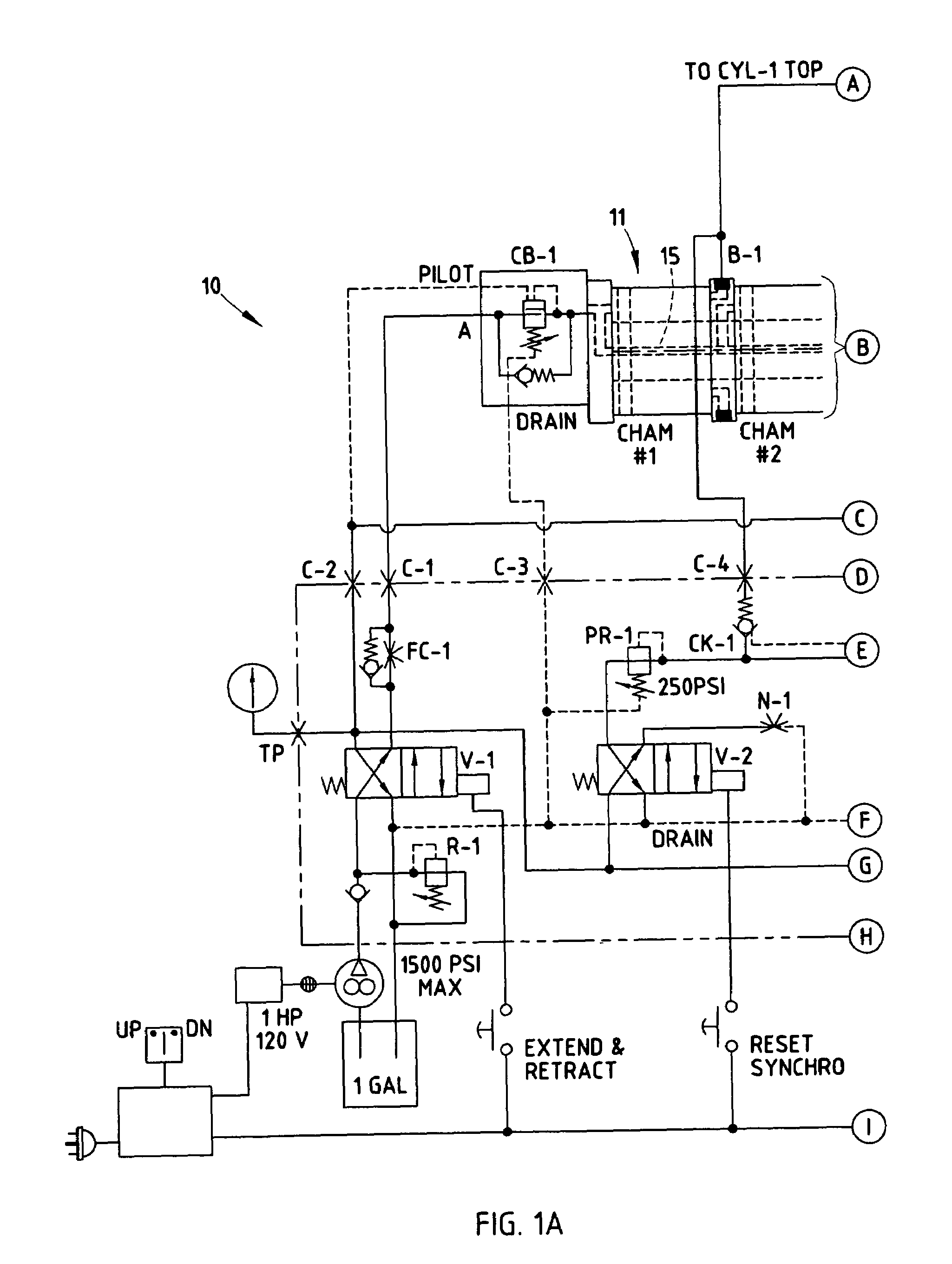
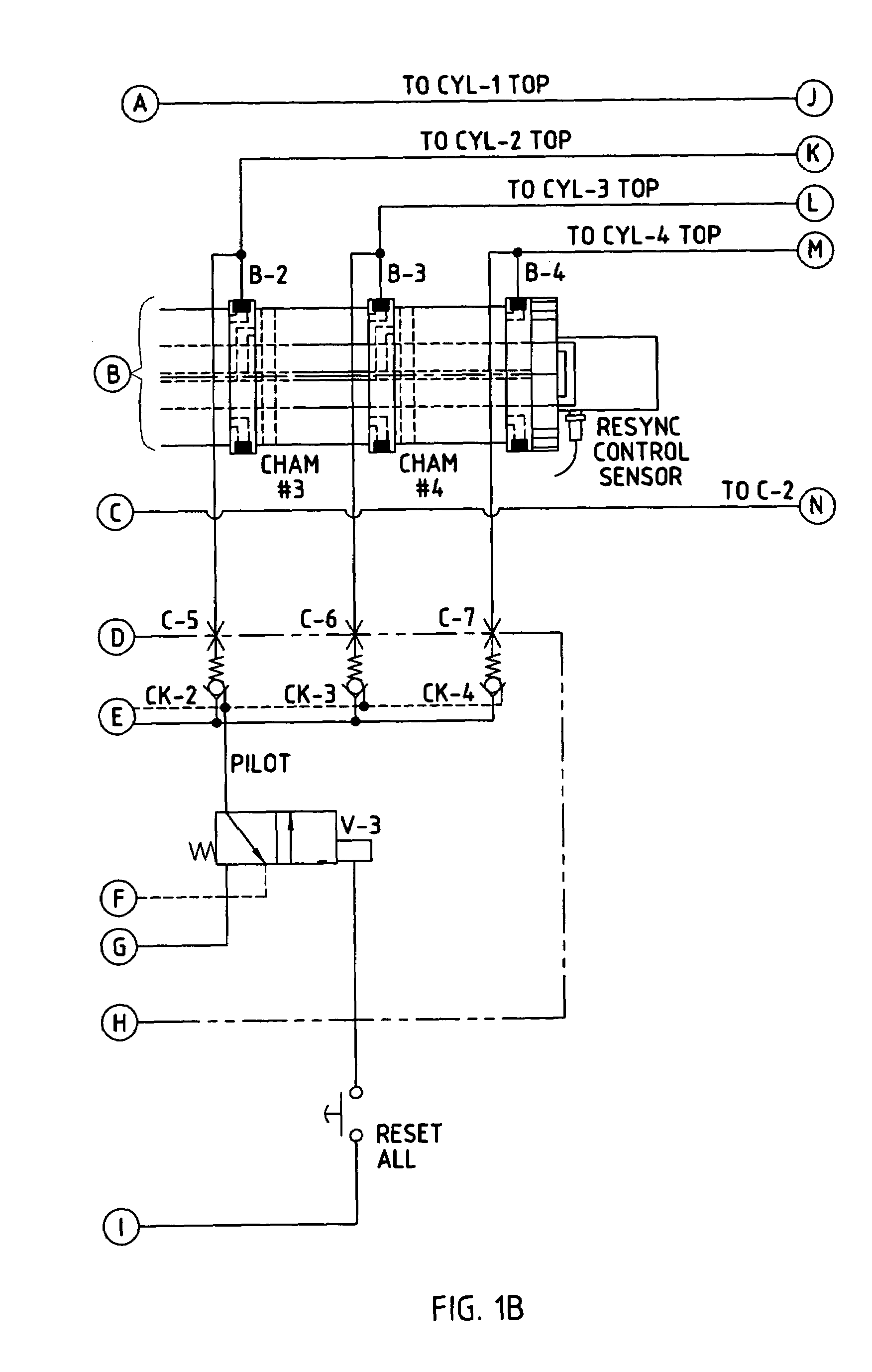
[0019]The present apparatus 10 (also called a “hydraulic system” herein) (FIGS. 1A–1B) includes a hydraulic circuit and components that achieve full and reliable synchronous operation of multiple (single and / or double acting) hydraulic cylinders. In the illustrated system, the cylinders used have similar areas in order to provide synchronized identical stroke actions.

[0020]The illustrated apparatus 10 (FIGS. 1A–1C) includes four cylinders CYL-1, CYL-2, CYL-3, CYL-4 for lifting a table having a support surface 12 uniformly in a level manner without binding, even where there is an unbalanced load such as a heavier load L1 in one location and a lighter load L2 in another location on the table or lift surface. The apparatus 10 includes a synchronizer 11 having four chambers CHAM#1–CHAM#4 operably connected to a top of each of the cylinders CYL-1–CYL-4 by individual hydraulic lines. The synchronizer 11 includes a supply-side end plate, and a series of (four) cylinder walls and (three) in...


PUM


Abstract

A lift table maintains levelness while lifting a support surface via two or more lift cylinder assemblies. A hydraulic circuit is connected to the cylinder assemblies, and includes synchronizer with multiple isolated chambers corresponding to the lift cylinder assemblies, a rod extending axially through the chambers, and pistons mounted on the rod and associated with the isolated chambers. An axial passageway extends continuously through the rod and is connected to first passageways for communicating hydraulic fluid to one side of the chambers. The hydraulic circuit operably connects a pump to the axial passageway of the synchronizer and to second passageways connected to the chambers and to the cylinder assemblies for controlling and providing synchronized movement of the at least two lift cylinder assemblies. The hydraulic circuit includes valving for an automatic re-synchronization cycle, fill cycle, and air purge cycle.

Description

[0001]This application is a continuation-in-part application of patent application Ser. No. 10 / 894,713, filed Jul. 20, 2004, entitled HYDRAULIC SYSTEM FOR SYNCHRONIZED EXTENSION OF MULTIPLE CYLINDERS, which in turn claims benefit under 35 USC 119(e) of provisional application Ser. No. 60 / 543,068, filed Feb. 9, 2004, entitled HYDRAULIC SYSTEM FOR SYNCHRONIZED EXTENSION OF MULTIPLE CYLINDERS, the entire contents of which are incorporated herein in their entirety.BACKGROUND[0002]The present invention relates to a hydraulic system for synchronized extension of multiple cylinders. For example, the present invention is useful on a lift table where table surface must be raised and / or lowered while maintaining levelness, despite non-uniform loads. However, the present apparatus is not believed to be limited to only this particular application, since distribution of identical amounts of hydraulic fluid can be used very effectively in many different applications. Also, the present invention i...

Claims


Application Information

Patent Timeline
Patent Type & Authority Patents(United States)
IPC IPC(8): F15B7/00F15B11/22F16D31/02
CPCF15B11/22F15B2211/40523
Inventor BAIR, EUGENE C.
Owner J R AUTOMATION TECH
Why Eureka
Try Eureka