
Method and apparatus for detection of fluid level in a container

a technology of fluid level and container, applied in the direction of liquid/fluent solid measurement, instruments, machines/engines, etc., can solve the problems of unattended, difficult to estimate exactly, and difficult to determine when all the fluid within the container has been dispensed, so as to reduce the effect of capacitance and accurately detect rapid changing fluid levels

Inactive Publication Date: 2006-10-31
ROCKY MOUNTAIN COMPOSITES
View PDF23 Cites 29 Cited by
  • Summary
  • Abstract
  • Description
  • Claims
  • Application Information

AI Technical Summary

Benefits of technology

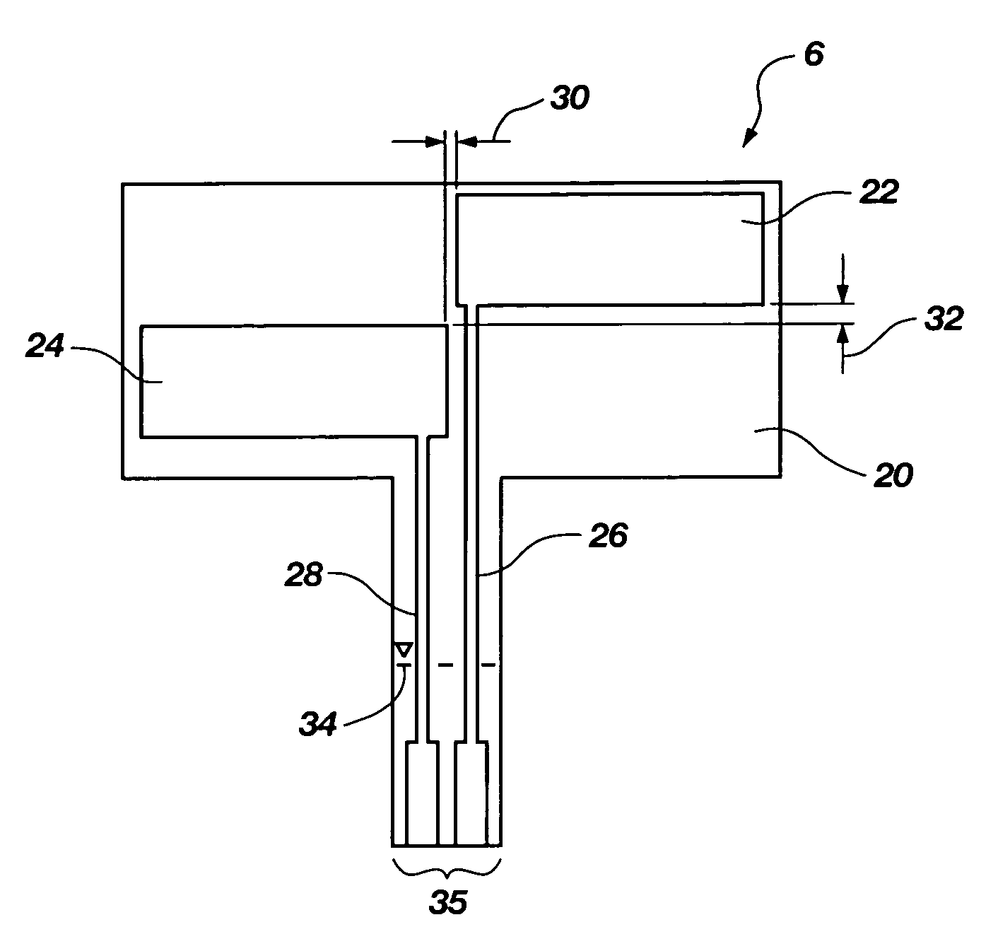
[0012]The present invention addresses the problems of conventional capacitance-type fluid level sensing devices by providing a reliable, relatively simple, capacitance-type level sensor system which is substantially less susceptible to false level readings attributable to the presence of a residual film of viscous fluid, such as blood, on an inner wall of a container to which the level sensor of the invention is affixed.
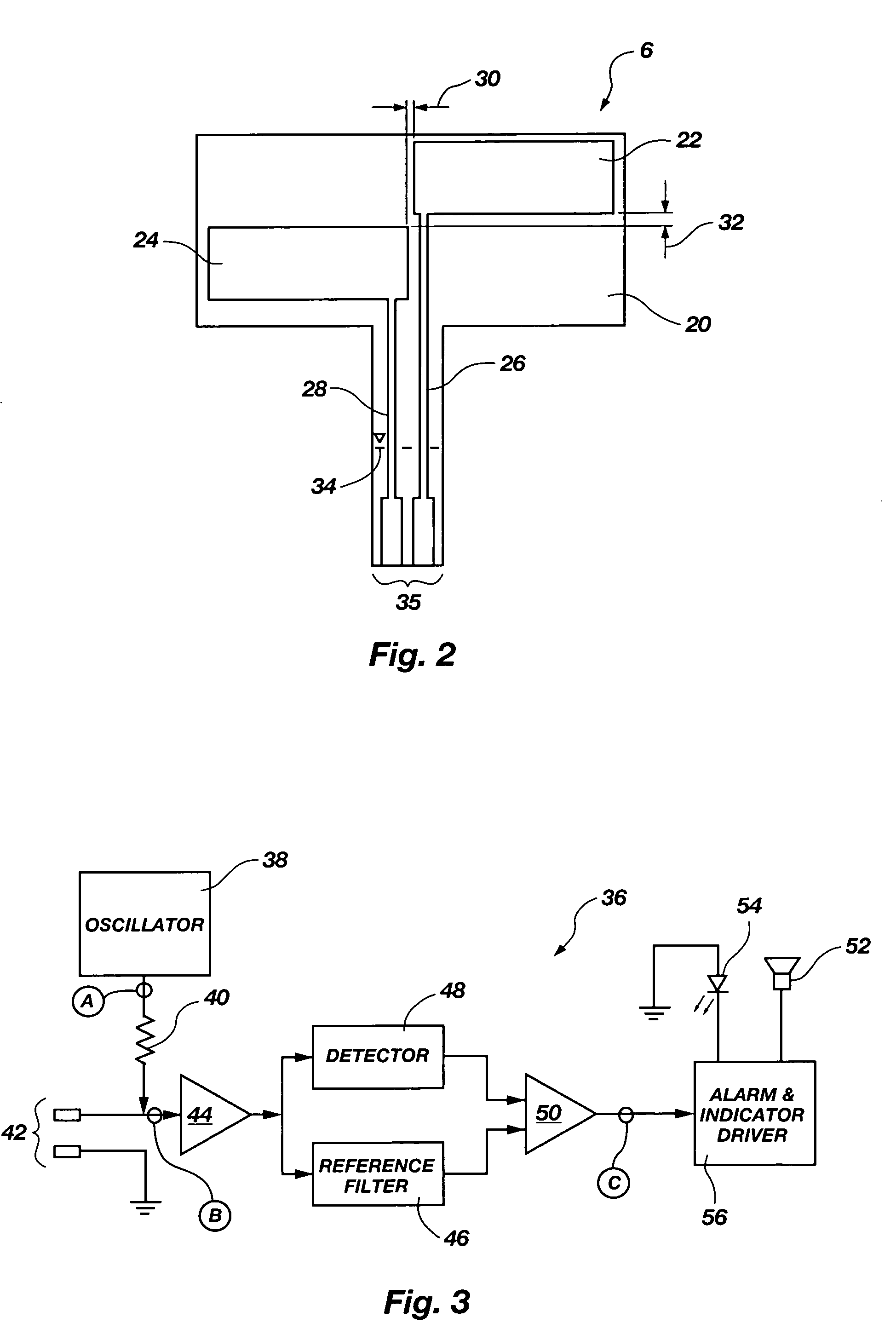
[0015]The size of the sensor in terms of plate length and vertical as well as any horizontal separation of the plates may be optimized for the system frequency and container wall material and thickness, as well as the nature of the fluid, the level of which is to be monitored. The plates of the sensor are arranged with a vertical separation to allow detection of a rapid decrease of fluid level where a residual layer or film of fluid is left on the container walls. Horizontal separation of the plates may be adjusted depending upon the resistance attributable to the fluid film on the interior of the container wall. The sensor is most preferably configured so that the capacitor plates are arranged with a vertical separation so that an upper plate is completely exposed and the film is allowed to dissipate while the fluid is still lowering over a second, lower plate. The plates may also be horizontally separated by at least a small distance, or at least not overlap horizontally, to maximize the film resistance between the sensors. The above-described sensor and control circuit configuration allows the level detection of blood and other conductive fluids that leave a conductive film on the container wall.
[0017]As noted previously, many fluids, particularly those of substantial viscosity, leave thin conductive films on the container walls that may take seconds, or even minutes, to thin to a level where a conventional capacitor-type level sensor may detect the change. To be able to accurately detect rapidly changing fluid levels in spite of the thin, conductive fluid film left on the container walls, several things should happen. First, as noted above, it is desirable to drive the sensor capacitance with a high frequency of about 4 MHz or greater. At lower frequencies, for example, 1 MHz, a residual film of blood on a container wall may give a false level reading, indicating erroneously that the blood level within the container is at or higher than the level of the sensor. The thin, conductive fluid film may be characterized as small capacitive electrodes extending through the resistive portion of the film. The film resistance and capacitances together act as a low pass filter. Therefore, increasing the frequency reduces the effect of the capacitance in the residual film adjacent the sensor.

Problems solved by technology

The containers themselves come in different sizes and shapes, and the fluids are administered to patients in widely varying flow rates which are often difficult to estimate exactly.
Consequently, without directly monitoring the container throughout its use, it is often difficult to determine when all of the fluid within a container has been dispensed.
It is detrimental to a patient to have the flow of an i.v. fluid come to a complete stop, unattended, because of complications which can occur from the stop of fluid flow.
Complications may include the clogging of the needle due to blood clotting, usually requiring reinsertion of a new needle, or blood passing out of the patient into the tubing.
The more frequently a needle is inserted and reinserted into a vein, the greater the risk for complications and infection.
However, a common concern associated with probe-type fluid level sensors and other sensors which must be placed on the inside of the container involves the risk of introducing contamination into the fluid.
For a hospital environment, particularly where fluids generally come in presterilized containers, introducing a probe into the fluid to determine its level is a great risk, and providing presterilized sensors already within the containers increases healthcare costs and requires hospitals to use common equipment for monitoring the sensors.
Therefore, increasing the frequency reduces the effect of the capacitance in the residual film adjacent the sensor.

Method used


Image

  • Method and apparatus for detection of fluid level in a container
  • Method and apparatus for detection of fluid level in a container
  • Method and apparatus for detection of fluid level in a container

Examples


Embodiment Construction

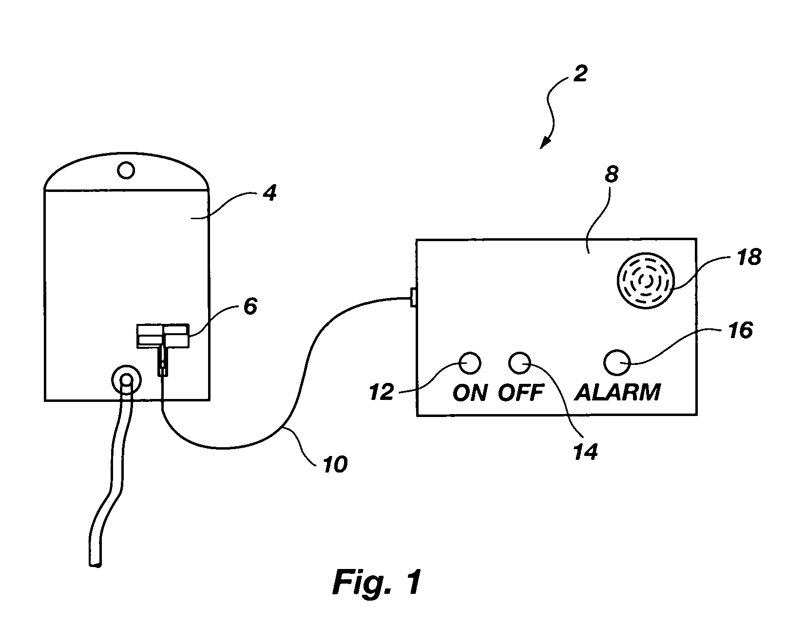
[0025]FIG. 1 depicts a fluid level sensor system 2 according to an embodiment of the present invention including a fluid container 4, a fluid level sensor 6, and detection and control circuitry housed in a control box 8. The fluid container 4 may be any fluid container having an electrically nonconductive wall such as both the rigid- and flexible-walled fluid containers commonly used in medical applications for storing blood, saline solution, human waste, or other fluids or mixtures. The fluid level sensor 6 may be affixed to a side of the fluid container 4 by an adhesive such as a pressure sensitive adhesive or other medical grade adhesive well known to one of ordinary skill in the art. The fluid level sensor 6 may be affixed to an outside wall of the fluid container 4 by medical personnel or other operator just before use, or formed on or within the fluid container wall as part of a manufacturing process and sold as an integral unit with the fluid container 4.

[0026]A conductive ca...


PUM


Abstract

A fluid level sensor is disclosed having first and second vertically and horizontally nonoverlapping electrode plates for placing on a wall of a fluid container. Most preferably, the plates are also vertically spaced from each other. The capacitor plates are driven by a high frequency square wave. By forming nonoverlapping plates and driving them using a high frequency, the level of a fluid within the container, particularly viscous fluid, is more accurately detected. Control and detection circuitry is also disclosed to trigger an alarm if the fluid level drops below a critical level within the container.

Description

PRIORITY CLAIM[0001]This application claims the benefit of the filing date of U.S. Provisional Patent Application Ser. No. 60 / 116,302, filed Jan. 19, 1999, for “METHOD AND APPARATUS FOR DETECTION OF A FLUID LEVEL IN A CONTAINER.”BACKGROUND OF THE INVENTION[0002]The present invention relates generally to determining a level of a fluid in a container. More specifically, the invention relates to a method and apparatus for more accurately sensing when a relatively rapid egress of a viscous fluid, such as blood, reaches a level within the container. The invention is particularly useful in applications wherein a reduction in fluid level leaves a film of the fluid on an inner wall of the container.STATE OF ART[0003]Both rigid and flexible containers are used in many industries to hold and dispense fluids of various natures. Accordingly, fluid level sensors and corresponding circuitry to indicate the quantity of fluid within a container or when the fluid reaches a particular level within th...

Claims


Application Information

Patent Timeline
Patent Type & Authority Patents(United States)
IPC IPC(8): G01F23/26
CPCG01F23/265G01F23/266G01F23/268
Inventor GRIFFITHS, ROBERT W.DRAPER, R. BRUCE
Owner ROCKY MOUNTAIN COMPOSITES
Learn More