Energy system for watercraft

a technology for watercraft and energy, applied in the direction of machines/engines, power plants using fuel cells, underwater equipment, etc., can solve the problems of not producing hazardous substances which endanger the environment, and achieve the effect of virtually no noise for propulsion

Inactive Publication Date: 2006-10-17
SIEMENS AG
View PDF10 Cites 15 Cited by
  • Summary
  • Abstract
  • Description
  • Claims
  • Application Information

AI Technical Summary

Benefits of technology

[0008]An embodiment of the invention is based on an object of providing a power system for watercraft which, in addition to providing power supply, transmits and converts without virtually any emissions and very largely without virtually any noise for propulsion of a watercraft, also which allows electrical devices within the watercraft to be supplied.

Problems solved by technology

When electrical power is produced in this way, hazardous substances which endanger the environment are not produced.

Method used


Image

  • Energy system for watercraft
  • Energy system for watercraft
  • Energy system for watercraft

Examples


Embodiment Construction

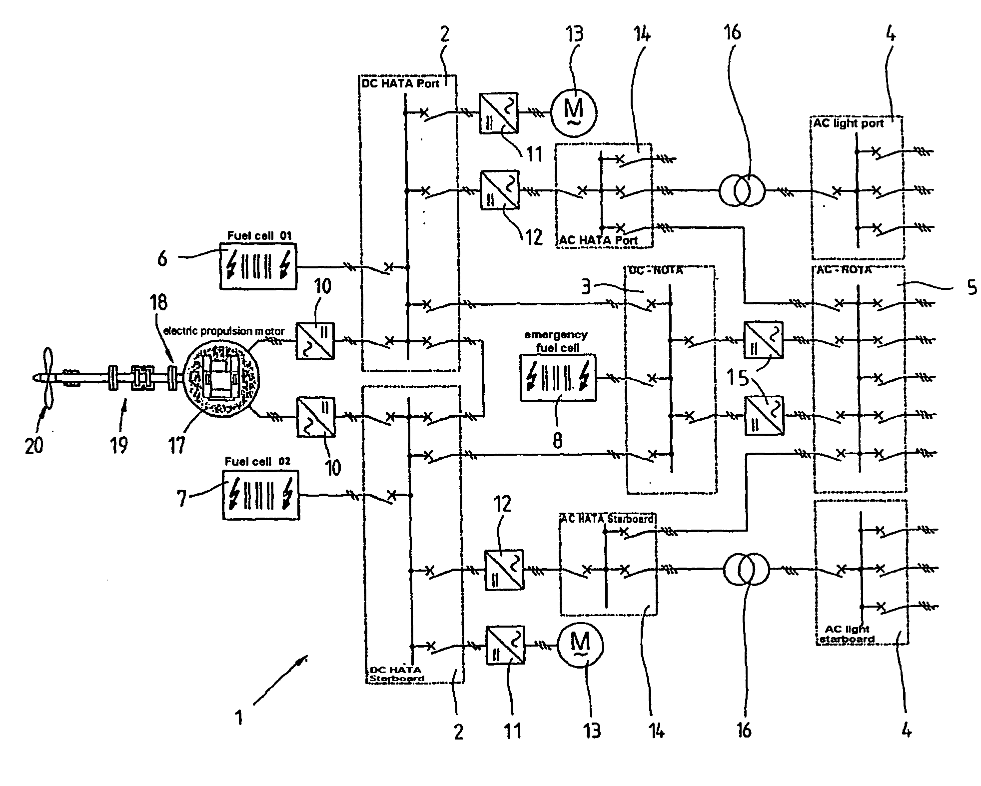
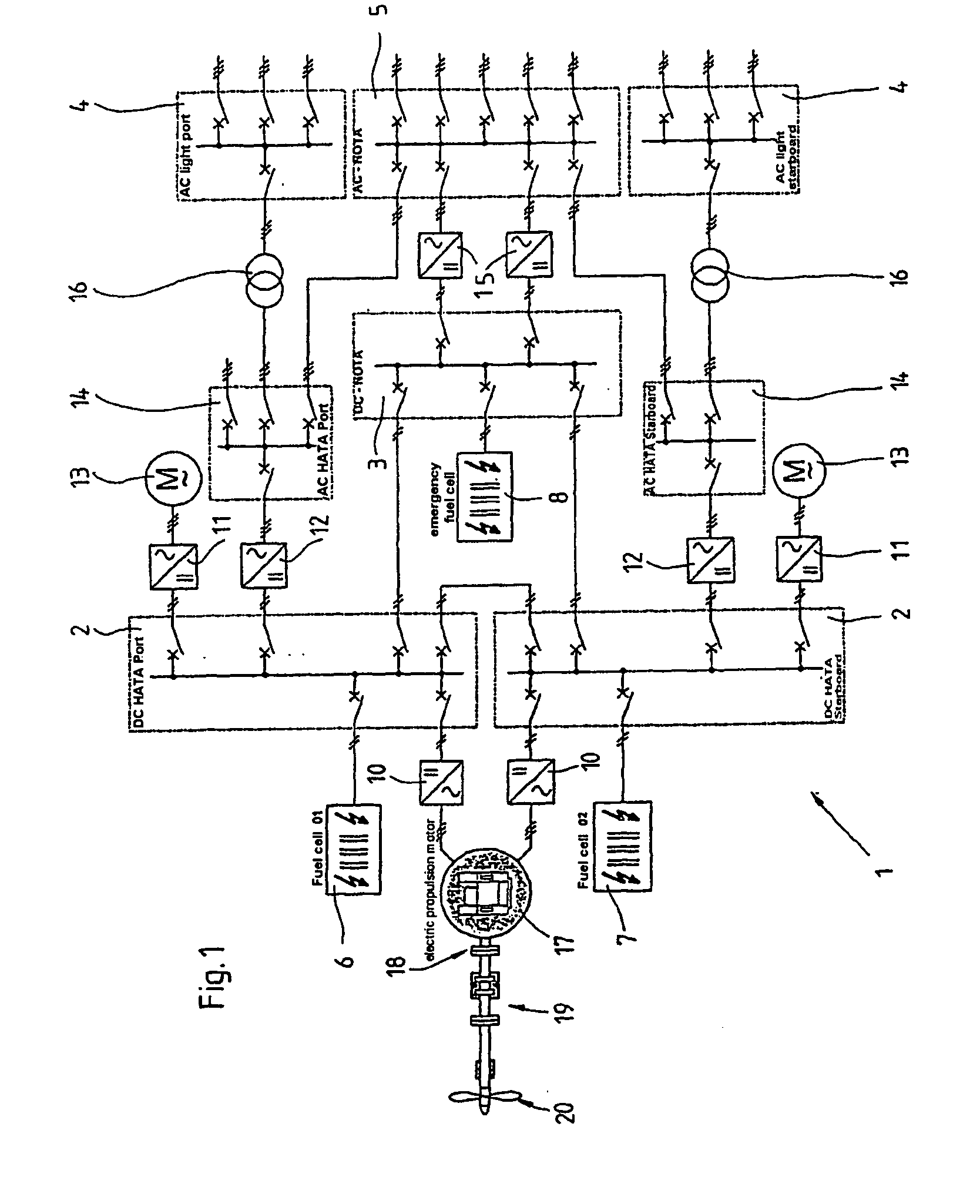
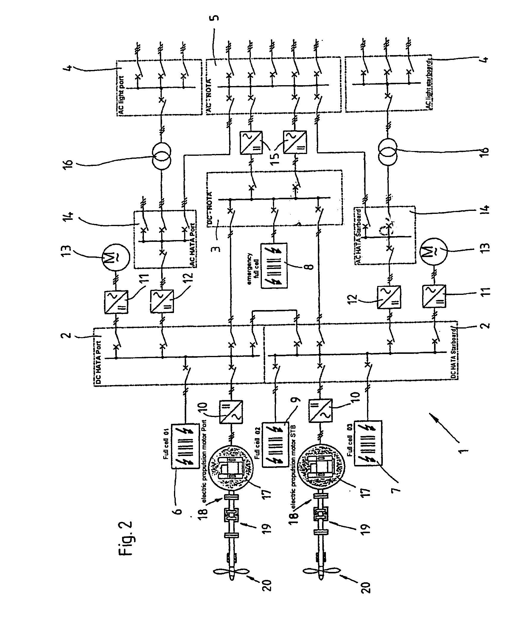
[0029]FIGS. 1 and 2 each show one exemplary embodiment of a power system 1 for watercraft. The power system 1 as shown in FIG. 1 is intended for a single-screw ship, and accordingly has an electrical propulsion system 17, which drives a ship propeller 20 via a shaft 18 with a thrust bearing 19. FIG. 2 shows a power system 1 for a twin-screw ship, with an electrical propulsion system 17 in each case being provided on the port side and on the starboard side, and in each case driving one ship propeller 20 via a shaft 18 and with a thrust bearing 19.

[0030]The electrical propulsion systems 17 as shown in FIGS. 1 and 2 are connected via a three-phase / three-phase network and an inverter unit 10 to a port and a starboard DC network 2, which are each supplied with electrical power by at least one respective fuel cell module 6 and 7, or 6, 7 and 9. The DC networks 2 in this case have two or more switching elements, which are switched by a control device (which is not shown explicitly here) as...


PUM

PropertyMeasurementUnit
mechanical poweraaaaaaaaaa
voltageaaaaaaaaaa
operating temperatureaaaaaaaaaa

Abstract

The invention relates to an energy system for watercraft, comprising at least one fuel cell module (6,7,8,9), preferably (a H2O2 fuel cell module, by which at least one electric drive (17) and at least one electrical consumer are supplied with electric energy via a supply network. Said electrical drive (17) is an AC drive that is connected to a DC network (2) of the supply network via at least one power inverter (10).

Description

[0001]This application is the national phase under 35 U.S.C. § 371 of PCT International Application No. PCT / DE02 / 00195 which has an International filing date of Jan. 22, 2002, which designated the United States of America and which claims priority on German Patent Application number DE 101 02 716.8 filed Jan. 22, 2001, the entire contents of which are hereby incorporated herein by reference.FIELD OF THE INVENTION[0002]The present invention generally relates to a power system for watercraft, in particular for ships, submarines and the like.BACKGROUND OF THE INVENTION[0003]Known watercraft of different types and sizes are normally propelled by fixed-pitch propellers, variable-pitch propellers, steering propellers as well as water jet systems. In this case, the mechanical power for propulsion is produced directly by internal combustion engines, for example Otto-cycle engines, diesel engines driven by way of heavy oil or light oil, or gas turbines. Fossil fuels are in this case used her...

Claims


Application Information

Patent Timeline
Patent Type & Authority Patents(United States)
IPC IPC(8): B63H21/20B63G8/08B63H21/17H01M8/04537H01M8/04955H01M8/0612H02J4/00
CPCB63G8/08B63H21/17H02J4/00B63H2021/003H01M8/04604H01M8/04955H01M8/0612H01M2250/20H02J2001/004Y02T70/5209Y02T70/5236Y02T90/32Y02T90/38Y02T90/46B60L2200/32H02J2300/30H02J2310/42Y02T70/50Y02T90/40Y02E60/50H02J1/10
Inventor RZADKI, WOLFGANG
Owner SIEMENS AG
Why Eureka
Try Eureka