
Programmable apparatus and method for body panel attachment

Active Publication Date: 2006-10-10
KUKA SYST NORTH AMERICA LLC
View PDF7 Cites 3 Cited by
  • Summary
  • Abstract
  • Description
  • Claims
  • Application Information

AI Technical Summary

Benefits of technology

[0031]The face plate is biased in a fully extended position such that the support surface protrudes axially beyond the pad contacting surface of the fixed anvil. The pad contacting surface is initially positioned apart from the work piece by an amount sufficient to ensure that support surface of the face plate does not prematurely engage the work piece. Thereafter, the apparatus of the present invention is moved along the axis of the fixed anvil toward the work piece in a direction generally perpendicular thereto. As the pad contacting surface approaches the predefined net reference position for a specific location, the support surface of the fully extended face plate comes into contact with the work piece. Additional advancement of the pad contacting surface toward the predefined net reference position overcomes the fully extended bias of the face plate, which effectively retracts the support surface of the face plate relative to the pad contacting surface of the fixed anvil.
[0046]It is another object to eliminate environmental and safety hazards associated with hydraulic oil in an automotive work environment.

Problems solved by technology

The method and apparatus of the aforesaid U.S. Pat. No. 4,438,971 does lead to precision in the positioning of plastic outer body panels to a relatively imprecisely positioned automotive inner body panel structure, but it requires the attachment of the plastic-filled attachment blocks to the inner body panel structure which adds to the material and processing costs.
Additionally, the subsequent milling of the plastic-filled attachment blocks generates scrap which is a mixture of a metal and the plastic filler material which, for the disposition of such scrap in an environmentally acceptable manner, involves additional expense and, in any case, the milling of the plastic-filled attachment blocks generates dust corresponding, mainly, to the composition of the plastic filler.
This is also objectionable on environmental and workplace health and safety grounds, unless strict precautions are followed in performing the milling and drilling of the plastic-filled attachment blocks.
However, this is a time-consuming and expensive procedure, and the attachment of such shims adds to the weight of the vehicle, an undesirable feature especially since it detracts from fuel economy.
Hydraulic equipment generally suffers from the disadvantages of significantly increased cost and maintenance requirements, slow operation, and auxiliary cooling requirements.
Additionally, hydraulic devices include a pressurized fluid, typically oil, that occasionally leaks as a result of long term use within the environment of an assembly operation.
Hydraulic leaks are messy, carcinogenic, environmentally unacceptable, and present a serious fire hazard.
The apparatus taught by Jackson is excessively complex and thus unnecessarily expensive and subject to failure.
This sensor device is a critical feature of the disclosure whereby any imprecision thereof is proportionally translated to the attachment pad formed on the inner body panel, and potentially gives rise to a visibly misaligned outer body panel.
As the effectiveness of the Jackson apparatus is predicated on the sensor device maintaining a high degree of precision over numerous cycles, the device becomes increasingly expensive.
Finally, Jackson does not disclose a device for analyzing the precision of the sensor device for purposes of error proofing, whereby loss of precision thereof will likely result in numerous defectively assembled automobiles before it can be identified and addressed.
The use of hydraulic cylinders by Copeman present the same disadvantages for this device as set forth with regard to the device of Dacey, Jr.
From the above, it can be appreciated that the prior art methods and apparatuses for precisely positioning and attaching a first member to an imprecisely located second member by forming a portion of the second member to a predetermined net reference position are not fully optimized.

Method used


Image

  • Programmable apparatus and method for body panel attachment
  • Programmable apparatus and method for body panel attachment
  • Programmable apparatus and method for body panel attachment

Examples


Embodiment Construction

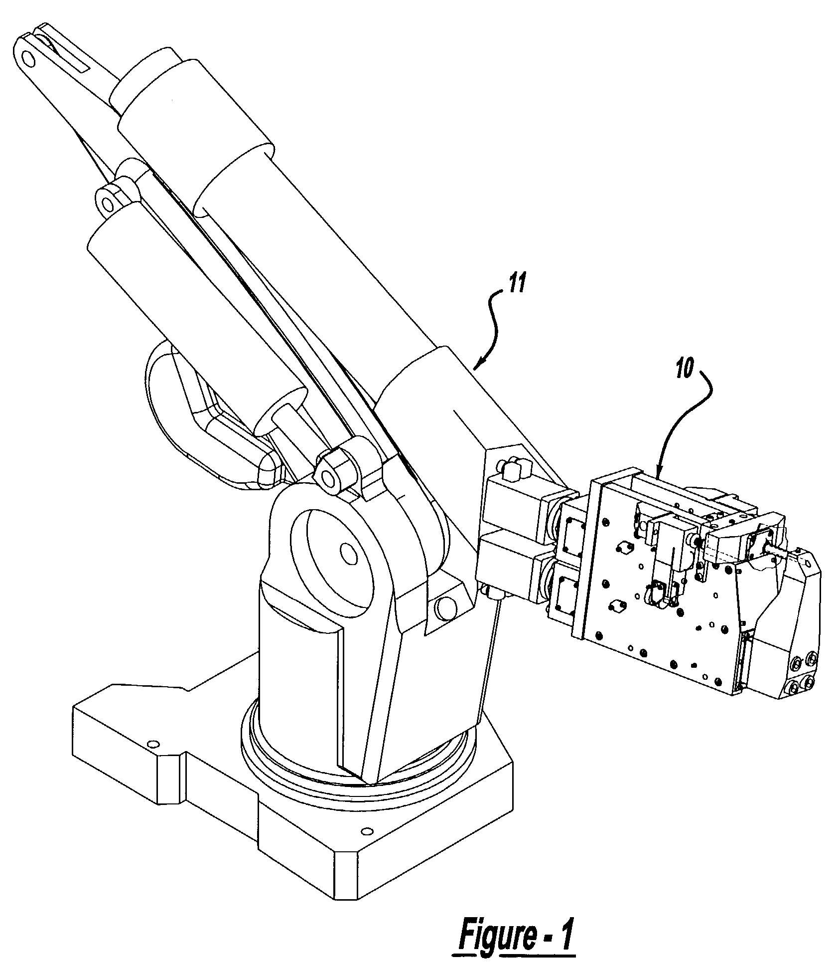
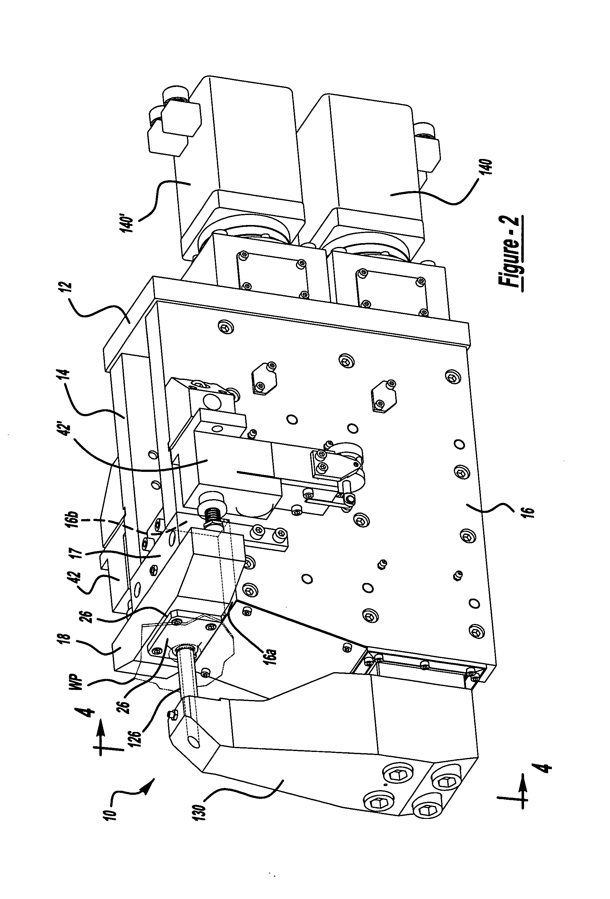
[0067]Referring now in detail to the Figures, there is shown in FIGS. 1 and 2 a net locating device in the form of a pad forming device 10 that is constructed in accordance with the present invention. According to the preferred embodiment, one or more programmable robots 11 move the pad forming device 10 into and out of working engagement with a work piece WP, and precisely position the pad forming device 10 relative to specific locations on the work piece WP. The pad forming device 10 is adapted to form an attachment pad P (shown in FIG. 7) at one or more specific locations on the work piece WP, such that the external surface of each attachment pad P is precisely located at a predefined net reference position independently defined for each location, and thereafter punch either a hole H (shown in FIG. 7) or slot (not shown) in the attachment pad P. As long as the work piece WP is within an acceptable tolerance range, it is provided with an attachment pad P having an external surface...


PUM

PropertyMeasurementUnit
Lengthaaaaaaaaaa
Sizeaaaaaaaaaa
Accelerationaaaaaaaaaa

Abstract

A method and apparatus for forming attachment pads in an inner body panel for the precise attachment of an outer body panel thereto. The apparatus positions a fixed anvil at a predefined net reference position while a face plate simultaneously “finds” the panel and is mechanically locked into position. Thereafter, the apparatus forms the inner body panel between a forming die and the fixed anvil. The face plate maintains the location of the surface metal around the die, resulting in the formation of a raised pad the outermost surface of which is at the predefined net reference position. A single such apparatus can form raised pads having different predefined net reference positions for different attachment locations. A reciprocating punch having a variable stroke length selectively provides either a hole or a slot in the raised pad.

Description

CROSS-REFERENCES TO RELATED APPLICATIONS[0001]Not applicable.FEDERALLY SPONSORED RESEARCH OR DEVELOPMENT[0002]Not applicable.REFERENCE TO A MICROFICHE APPENDIX[0003]Not applicable.BACKGROUND OF THE INVENTION[0004]1. Field of the Invention[0005]This invention relates to the precise attachment of a first member to a second member, and provides a method of and apparatus for reforming the second member by a variable magnitude depending on the actual position of the second member relative to a predefined net reference position. The invention relates, in particular, to the precise attachment of an outer body panel member of an automotive vehicle to an imprecisely located element of an inner body panel structure.[0006]2. Description of the Related Art[0007]In the automotive industry, the assembly of vehicles involves the attachment of outer body panels to inner body panels or body structures. It is therefore important that the inner body panel attachment positions be precisely located with...

Claims


Application Information

Patent Timeline
IPC IPC(8): B21D28/34B23P19/06
CPCB21D22/04B21D28/26Y10T83/9387Y10T83/9432
Inventor SAVOY, MARK A.
Owner KUKA SYST NORTH AMERICA LLC
Learn More