Transmitting/receiving filter device and communication device

Active Publication Date: 2006-10-03
MURATA MFG CO LTD
View PDF8 Cites 20 Cited by
  • Summary
  • Abstract
  • Description
  • Claims
  • Application Information

AI Technical Summary

Benefits of technology

[0009]With the element that prevents positive feedback of the received signal, positive feedback in which the received signal returns to the input side of the first transmission path via the second transmission path does not occur, thus preventing oscillation.
[0011]With this structure, the received signal passing through the first transmission path is transmitted to the second port, and is not transmitted to the second transmission path. Positive feedback of the received signal does not occur, thus preventing oscillation.

Problems solved by technology

However, if the amount of attenuation in the vicinity of the receiving frequency band of the transmission filter is not satisfactory, the output signal of the amplification circuit LNA is oscillated because of positive feedback in the path of Rx2→Tx1→Rx1→LNA.
As a result, there arises a problem in that insertion loss (IL), nose figure (NF), and group delay (GD) characteristics in the transmission frequency band or the receiving frequency band are degraded.

Method used


Image

  • Transmitting/receiving filter device and communication device
  • Transmitting/receiving filter device and communication device
  • Transmitting/receiving filter device and communication device

Examples


first embodiment

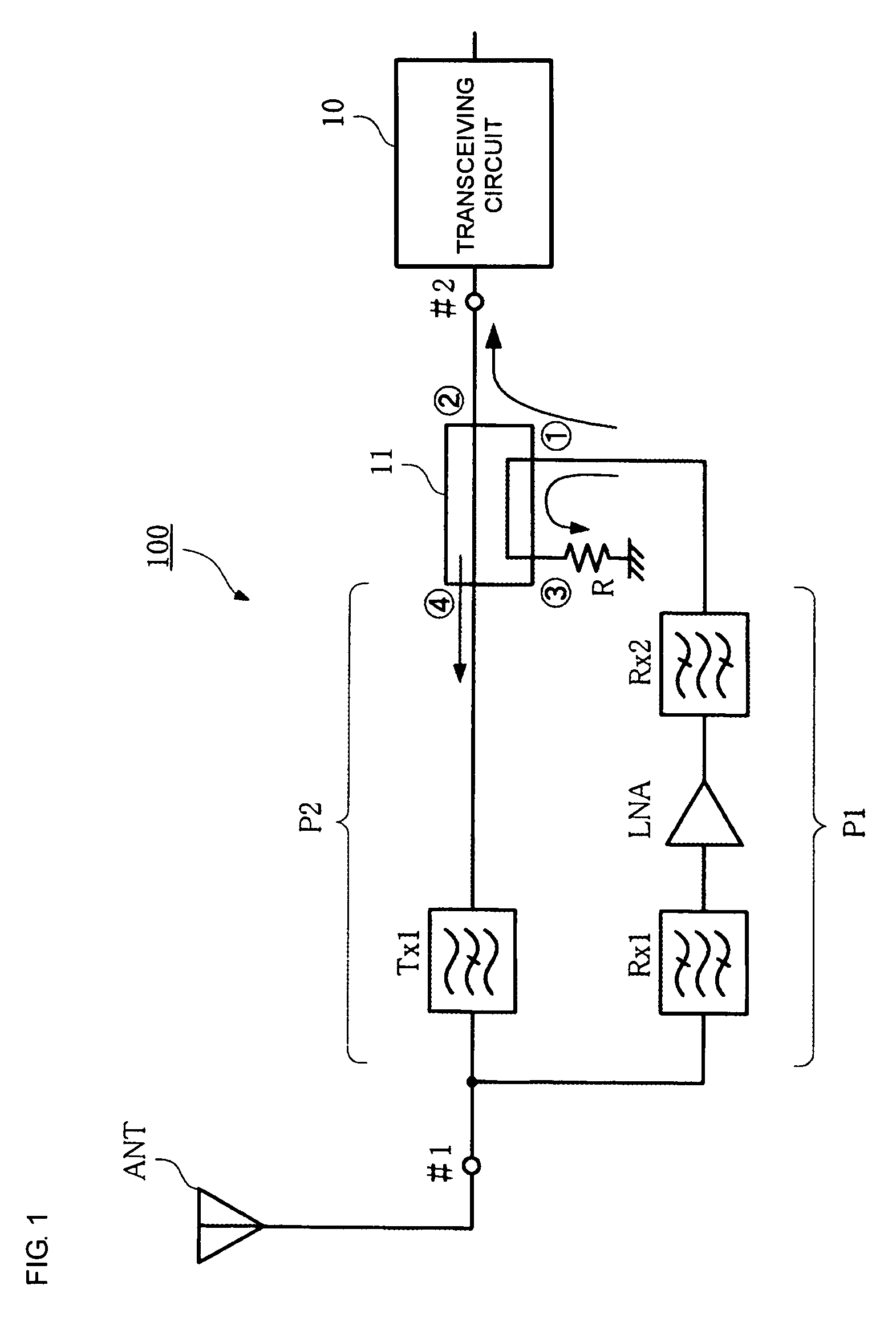
[0025]FIG. 1 shows the structure of a communication apparatus having a transceiving filter device according to a In FIG. 1, reference symbol ANT denotes an antenna of a base station, and a transceiving circuit 10 is a circuit that transmits and receives a communication signal in the base station. In FIG. 1, the components other than the antenna ANT and the transceiving circuit 10 form a transceiving filter device 100.

[0026]The antenna ANT is connected to a first port #1 of the transceiving filter device 100, and the transceiving circuit 10 is connected to a second port #2 of the transceiving filter device 100. The transceiving filter device 100 and the antenna ANT are disposed on the tower top portion of the base station. Reference numerals Rx1 and Rx2 denote receiving filters having a bandpass characteristic that allows a receiving-frequency-band signal to pass and that stops a transmission-frequency-band signal. Reference symbol LNA denotes a low-noise amplification circuit. The ...

second embodiment

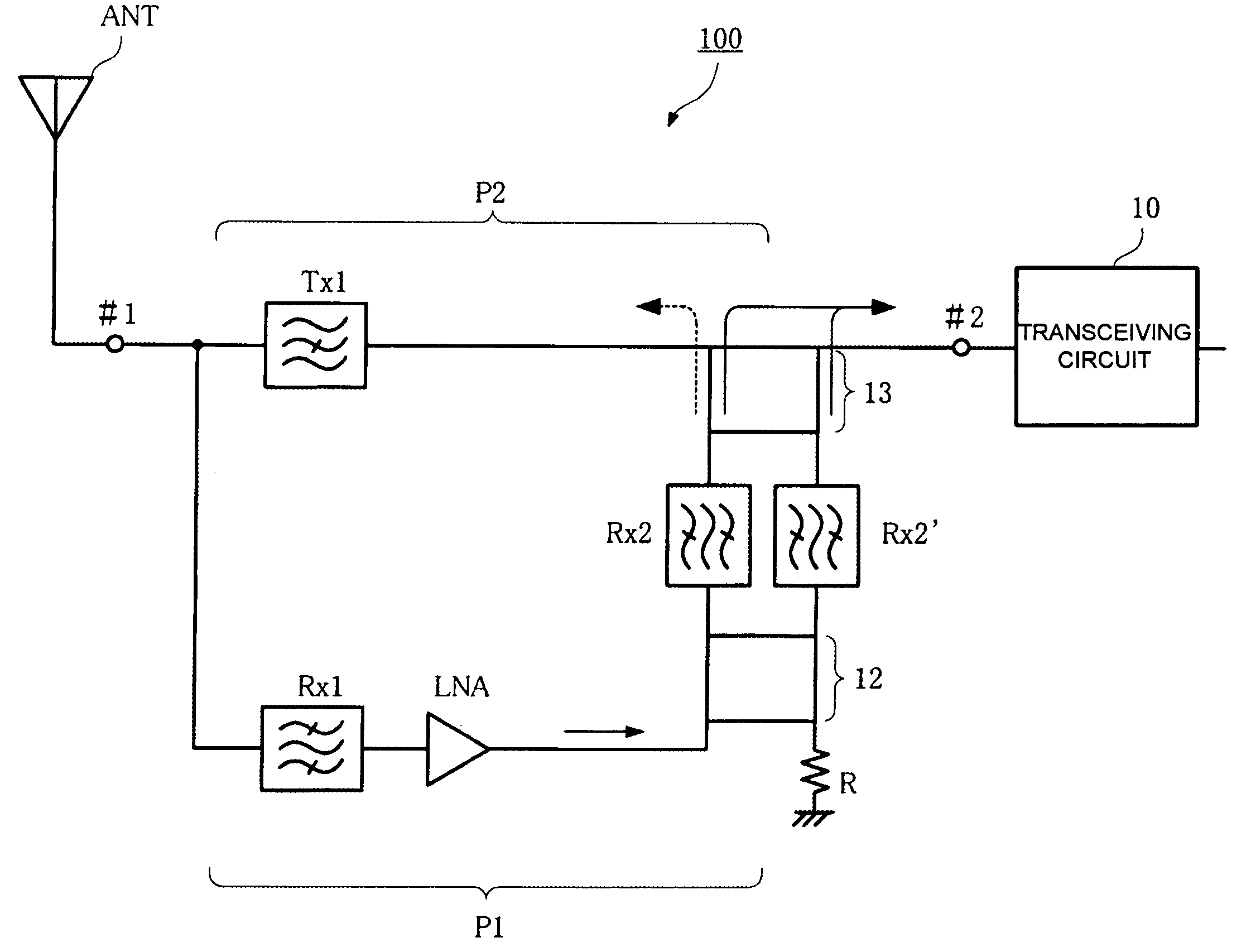
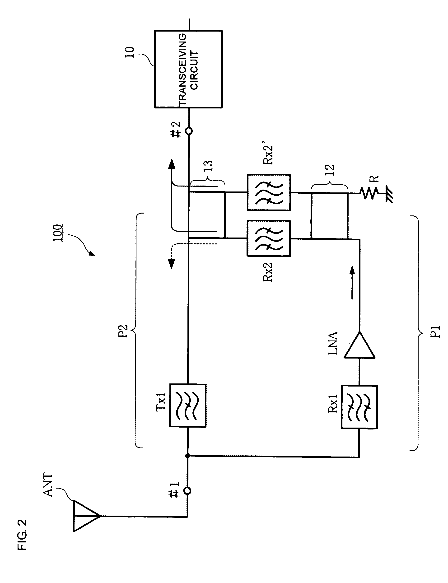
[0030]FIG. 2 shows the structure of a communication apparatus having a transceiving filter device according to a In this example, 90° hybrid circuits 12 and 13 and receiving filters Rx2 and Rx2′ are disposed at the connection between the first transmission path P1 and the second transmission path P2.

[0031]The 90° hybrid circuits (hereinafter referred to simply as “hybrid circuits”) 12 and 13 are power-halving circuits having directivity in the signal transmission direction. The hybrid circuit 12 power-halves the received signal amplified by the amplification circuit LNA, and the hybrid circuit 13 outputs the received signal which has passed through the receiving filters Rx2 and Rx2′ to the port #2. As described below, the received signal which has passed through the receiving filters Rx2 and Rx2′ is not transmitted to the second transmission path P2.

[0032]The receiving filters Rx2 and Rx2′ disposed between the two 90° hybrid circuits 12 and 13 pass the receiving frequency band and ...

third embodiment

[0036]The structure of a communication apparatus having a transceiving filter device will now be described with reference to FIGS. 4 through 6.

[0037]FIG. 4 is a block diagram of the transceiving filter device. The basic structure of this transceiving filter device is the same as that of the transceiving filter device shown in FIG. 2. In this example, one of two 90° hybrid circuits, that is, a 90° hybrid circuit 14, has a two-stage structure. The structure of the remaining components is similar to that shown in FIG. 2.

[0038]FIG. 5 shows the structure of the hybrid circuit 14 portion. Each of lines L1 through L7 has an electrical length of one-quarter the wavelength of the transmission frequency. The impedances of these lines are as follows:

[0039]L1 through L4: 35.95 Ω

[0040]L5 and L6: 105.23 Ω

[0041]L7: 47.26 Ω

[0042]FIG. 6 shows characteristics of the two-stage hybrid circuit, in which the y-axis designates the transmission loss or the reflection loss, expressed in dB. The center freq...


PUM


Abstract

First and second transmission paths P1 and P2 are disposed between a first port #1 connected to an antenna ANT and a second port #2 connected to a transceiving circuit 10. The first transmission path P1 includes receiving filters Rx1, Rx2, and Rx2′, an amplification circuit LNA, and 90° hybrid circuits 12 and 14. The second transmission path P2 includes a transmitting filter Tx1. A received signal amplified by the amplification circuit LNA is transmitted to the port #2 via the 90° hybrid circuits 12 and 14, but is not transmitted to the second transmission path P2. A transmission signal is transmitted from the port #2 to the second transmission path P2. This prevents oscillation of the received signal due to positive feedback. A transceiving filter device that prevents degradation in the insertion loss, noise figure, and group delay characteristics in the transmission frequency band or the receiving frequency band and that prevents oscillation, and a communication apparatus using the transceiving filter device are provided.

Description

TECHNICAL FIELD[0001]The present invention relates to a transceiving filter device that selectively passes a transmission signal and a received signal, and to a communication apparatus including the transceiving filter device.BACKGROUND ART[0002]In the related art, a base station in a mobile communication system includes a transceiving filter device having an amplification circuit between a tower antenna and a transceiving circuit for amplifying a received signal.[0003]For example, Patent Document 1 (International Publication No. 02 / 31997 pamphlet) shows a transceiving filter device having first and second transmission paths between a first port connected to an antenna and a second port connected to a transceiving circuit.[0004]This structure is shown in FIG. 8. In FIG. 8, reference symbol ANT denotes an antenna, reference numeral 10 denotes a transceiving circuit, reference numeral P1 denotes a first transmission path that allows a received signal to pass, and reference numeral P2 ...

Claims


Application Information

Patent Timeline
IPC IPC(8): H04B1/16H03H7/01H04B1/44H04B1/48H04B1/52
CPCH04B1/48H04B1/52H04B1/50
Inventor HATTORI, JUNKUBO, HIROYUKI
Owner MURATA MFG CO LTD
Why Eureka
Try Eureka