Motor control apparatus and motor control apparatus control method

Active Publication Date: 2019-07-18
MITSUBA CORP
View PDF0 Cites 0 Cited by
  • Summary
  • Abstract
  • Description
  • Claims
  • Application Information

AI Technical Summary

Benefits of technology

The present invention provides a low-cost motor control apparatus that can correct position detection signals and switch power distribution patterns accurately to prevent oscillation and abnormal sounds. The technical effects include improved accuracy and efficiency in motor control.

Problems solved by technology

In such a case, when switching the output of the drive signal for each Hall edge, there is a possibility that the switching may affect the motion of the brushless motor, and oscillation or an abnormal sound may occur.
However, the motor drive apparatuses described in Patent Documents 1, 2 do not have a configuration in which the position detection signal is corrected for each Hall edge that represents switching of a Hall stage and which switches a power distribution pattern on the basis of the corrected position detection signal, and therefore, it is impossible to prevent oscillation and an abnormal sound from occurring with good accuracy.

Method used


Image

  • Motor control apparatus and motor control apparatus control method
  • Motor control apparatus and motor control apparatus control method
  • Motor control apparatus and motor control apparatus control method

Examples


Embodiment Construction

[0035]Hereinafter, the present invention is described according to an embodiment, but the present invention is not limited to the following embodiment. Further, all of the combinations of features described in the embodiment are not necessarily indispensable for solving the problem addressed by the invention. In the drawings, the same reference numerals may be given to the same or similar parts, and redundant descriptions may be omitted. The shape, size, and the like of an element in the drawing may be exaggerated for clear description.

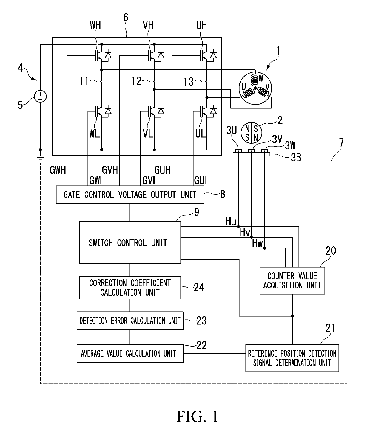
[0036]A motor control apparatus in an embodiment is a motor control apparatus that is configured to perform a power distribution control on three-phase coils of a brushless motor and that is configured to perform a rotation control of a rotor, the motor control apparatus including: a plurality of switching elements that are arranged to be capable of switching a current which is allowed to flow through the coils; a plurality of sensors each of which is...


PUM


Abstract

A motor control apparatus includes a control part. The control part includes: a gate control voltage output unit that outputs a drive signal based on a corrected Hall edge that constitutes each of six Hall stages; a counter value acquisition unit that acquires a counter value which is a time period of the Hall stage and which is represented by a time period between two Hall edges from the position detection signal; and a switching control unit that allows a value obtained by multiplying a previous counter value of each of the Hall stages by a preset correction coefficient to be a first delay time of each of current Hall edges and allows the gate control voltage output unit to output the drive signal based on each of the Hall edges obtained by correcting each of the Hall edges corrected by the first delay time by a second delay time that advances a Hall edge corresponding to a predetermined sensor among the plurality of sensors.

Description

TECHNICAL FIELD[0001]The present invention relates to a motor control apparatus and a motor control apparatus control method.[0002]Priority is claimed on Japanese Patent Application No. 2016-185004 filed on Sep. 23, 2016, the contents of which are incorporated herein by reference.BACKGROUND[0003]A brushless motor includes a stator having three-phase coils U, V, W and a rotor having a field permanent magnet. A sensor magnet that is rotated together with the rotor is attached to a rotation shaft of the rotor. The sensor magnet is magnetized by S and N poles alternately in a rotation direction. Three Hall sensors that detect a rotation position are attached to the vicinity of the sensor magnet at an interval of 120° in the rotation direction such that it is possible to detect the switching of magnetic poles of the sensor magnet.[0004]In a motor control apparatus that performs a drive control of the brushless motor, by outputting a power distribution pattern associated with Hall stages ...

Claims


Application Information

Patent Timeline
IPC IPC(8): H02P27/16H02P6/16H02K29/08H02K11/215H02M7/5387
CPCH02P27/16H02P6/16H02K29/08H02K11/215H02M7/53871H02M7/5395H02M7/48
Inventor IKEDA, TAKESHI
Owner MITSUBA CORP
Why Eureka
Try Eureka