
Circuit for generating a centered reference voltage for a 1T/1C ferroelectric memory

a ferroelectric memory and reference voltage technology, applied in the field of ferroelectric memories, can solve the problems of time reliability problems, loss of a certain amount of signal margin for using these prior art reference circuits, and limited range of reference voltage selection, so as to maximize signal margin and cost-free

Active Publication Date: 2006-10-03
INFINEON TECH LLC
View PDF15 Cites 13 Cited by
  • Summary
  • Abstract
  • Description
  • Claims
  • Application Information

AI Technical Summary

Benefits of technology

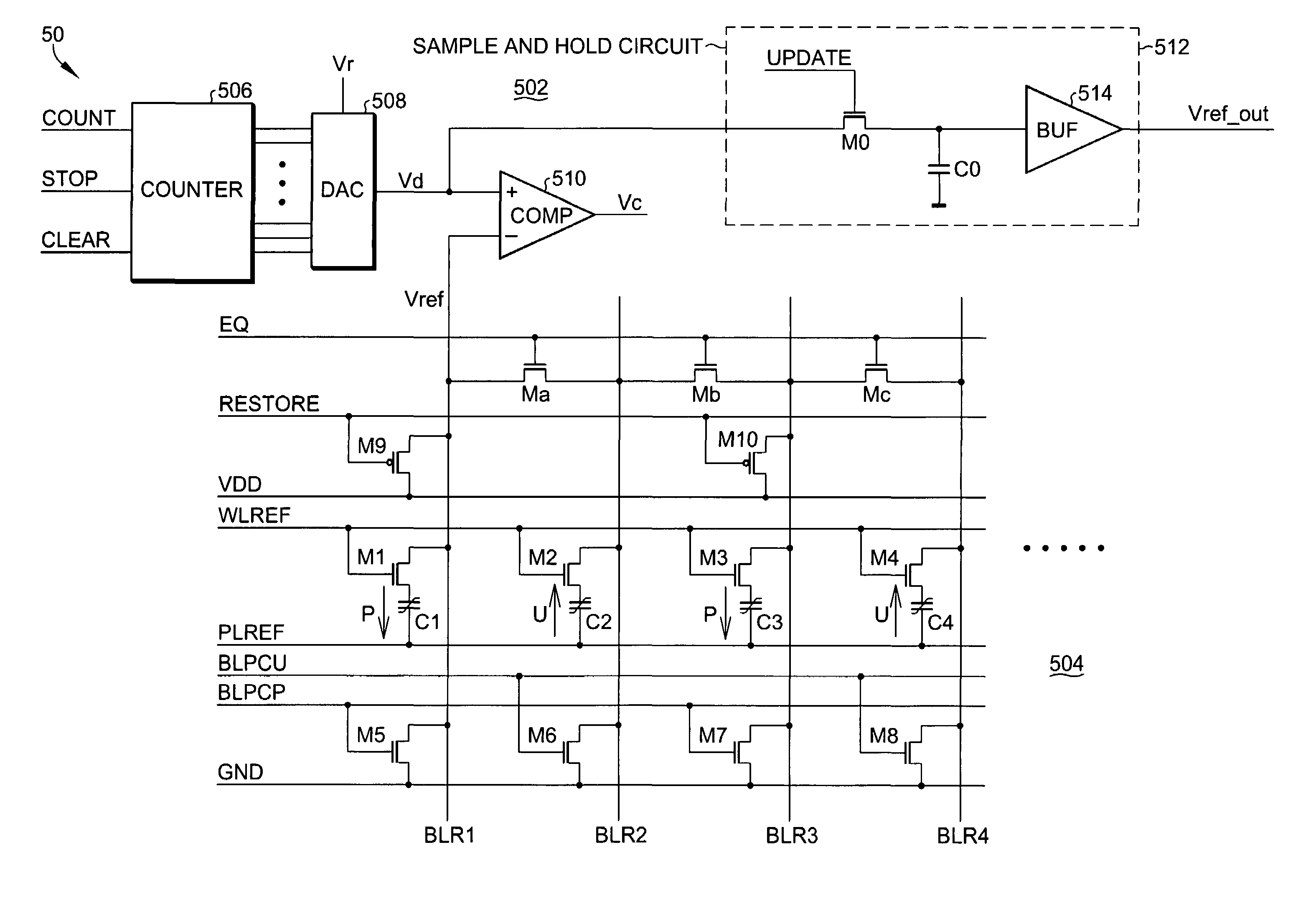
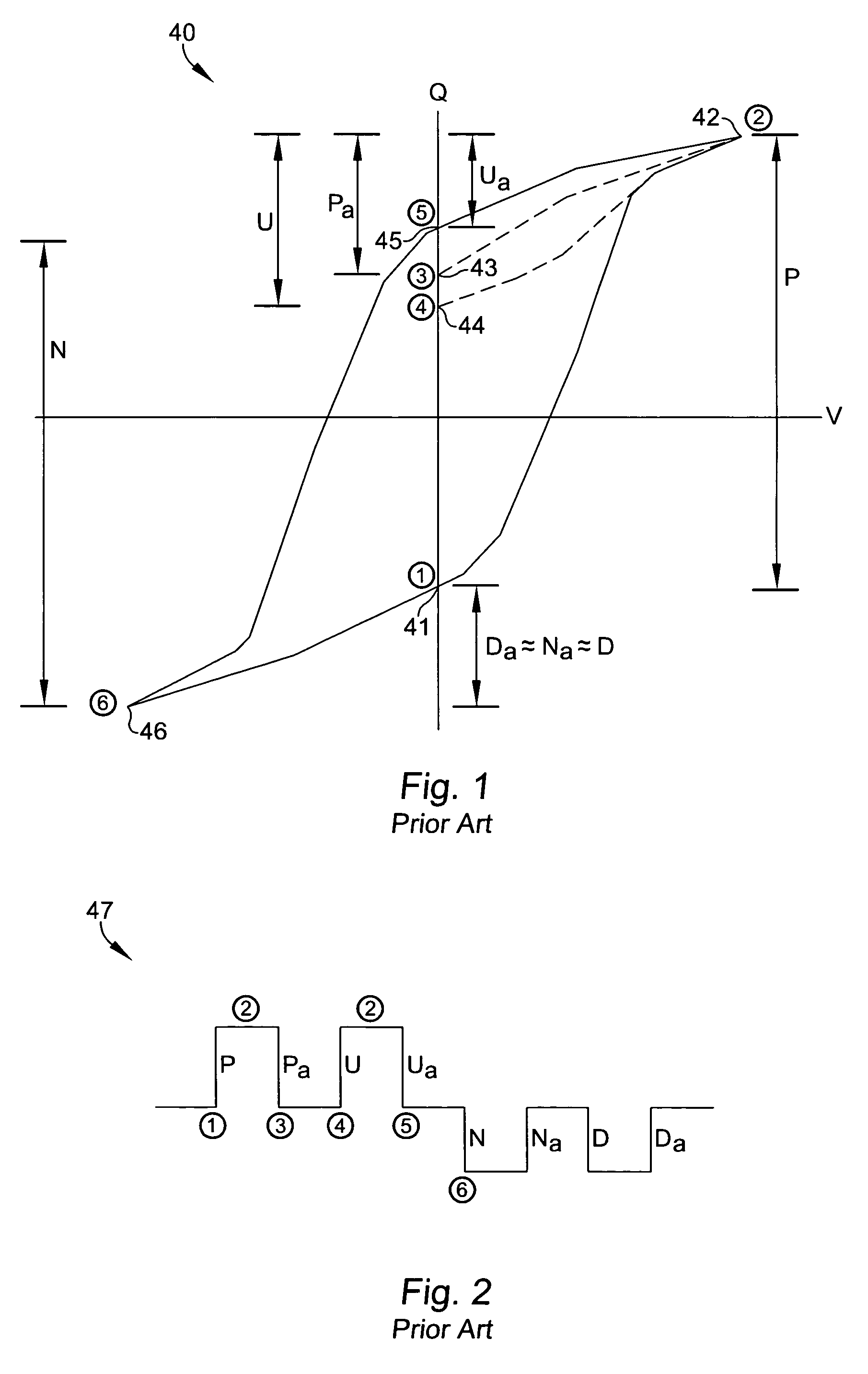
[0014]According to an embodiment of the present invention, a ferroelectric reference circuit generates a reference voltage proportional to a (P+U) / 2 charge term and is automatically centered between the bit line voltages corresponding to the P term and the U term across wide temperature and voltage ranges. To avoid fatiguing the reference ferroelectric capacitors generating the (P+U) / 2 charge term, the reference voltage is refreshed periodically, such as once every millisecond. To eliminate the variation of the reference voltage due to the leakage in the ferroelectric capacitors during this period of time, the reference voltage generated from the reference ferroelectric capacitors is digitized when it is refreshed. The digital value is fixed and converted to an analog value which is then fed into sense amplifiers for resolving the data states. The reference voltage is automatically at the center of the switching (P) and non-switching (U) signals at any temperature and voltage, therefore the reference is signal margin “cost-free” and the signal margin is maximized.
[0016]The reference voltage of the present invention is kept at the same voltage between refreshes, so no extra time is needed to generate a reference voltage after chip enable as with some prior art reference circuits. Thus, the reference circuit of the present invention is suitable for fast memory operation.
[0018]In a ferroelectric memory using the reference circuit of the present invention, retention time is maximized due to the fact that the (P+U) / 2 term is constant for same state and opposite state scenarios. After imprint, the increase in the U term is equivalent to the decrease in the P term. In other words, the reference voltage generated in the present invention is at the center of the P and U terms, even for an imprinted capacitor.

Problems solved by technology

Therefore, in prior art designs, the reference voltage selection is limited to a reduced range in order for memory parts to work at a low temperature and low voltage and a high temperature and high voltage.
In other words, the loss of a certain amount of signal margin is the cost for using these prior art reference circuits.
One of the long time reliability issues for ferroelectric reference circuits and ferroelectric memories in general is imprint.
However, the ferroelectric memory cells use the “P” and “U” terms, which do have the potential of fatigue.
If, on the other hand, a reference is constructed that uses the P and U terms in order to track the memory cells, then the reference cell capacitor will fatigue, and the memory part will prematurely fail.
Therefore, reference circuits that use the P and U terms, but have a reference capacitor that is accessed every time that a memory cell on the same column or same row is accessed, are not ideal for a commercial ferroelectric memory.
Another disadvantage in prior art reference circuits is that the optimized number of reference capacitors (or the size of reference capacitors, or the scaling factor) might be different from lot to lot.
Additional cost is required to determine the optimized reference for each lot.

Method used


Image

  • Circuit for generating a centered reference voltage for a 1T/1C ferroelectric memory
  • Circuit for generating a centered reference voltage for a 1T/1C ferroelectric memory
  • Circuit for generating a centered reference voltage for a 1T/1C ferroelectric memory

Examples


Embodiment Construction

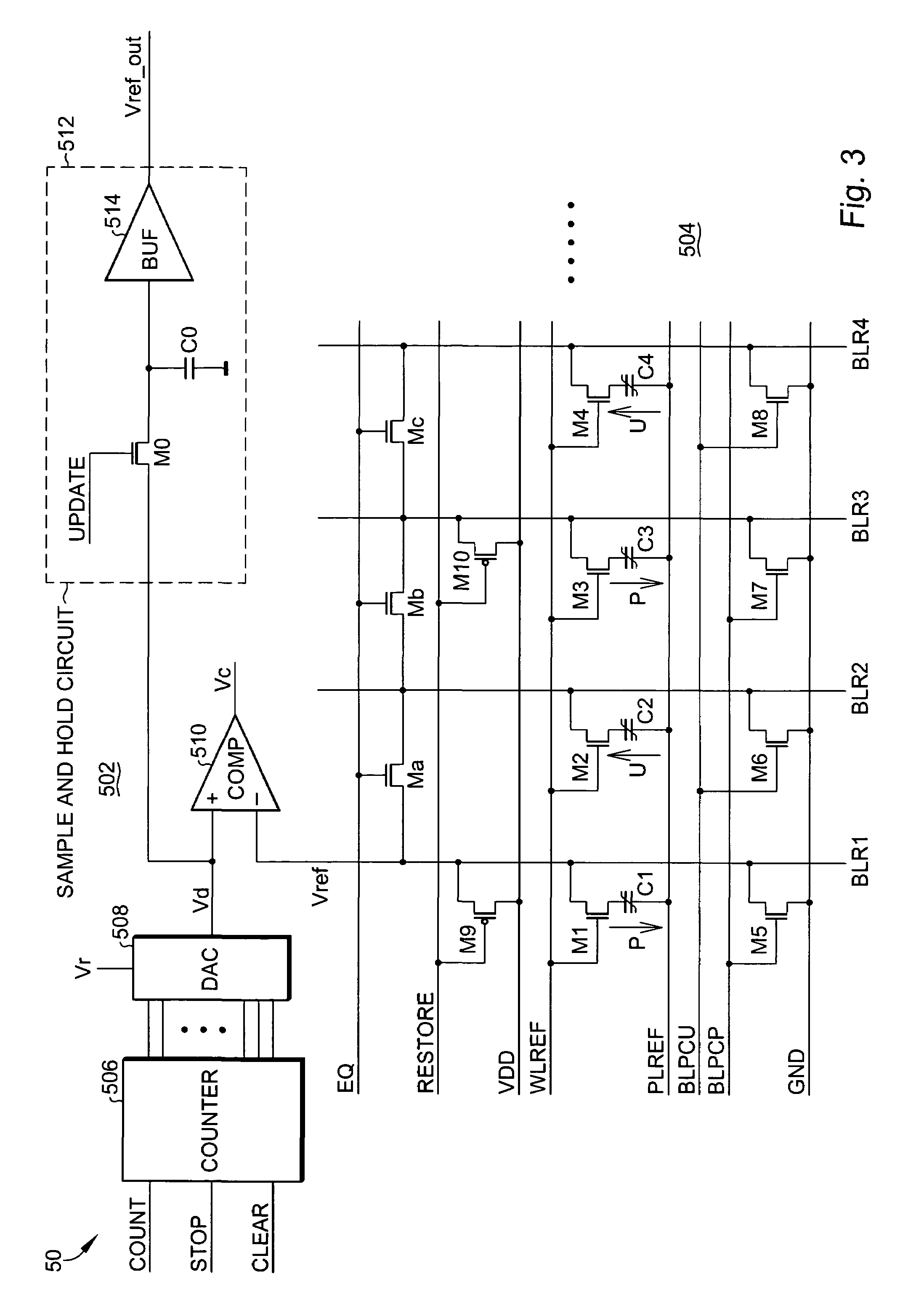
[0025]Referring now to FIG. 3, a reference circuit 50 for a ferroelectric memory includes a reference generating circuit 504 for generating a ferroelectric reference voltage and an “updating” or refresh circuit 504 coupled to the reference generating circuit through the VREF line for providing a periodically updated version of the ferroelectric reference voltage at the VREF_OUT output.

[0026]The reference generating circuit 504 includes at least two ferroelectric reference cells, each including a transistor and a ferroelectric capacitor. A first ferroelectric reference cell includes transistor M1 and ferroelectric capacitor C1. A second ferroelectric reference cell includes transistor M2 and ferroelectric capacitor C2. Any even number of ferroelectric reference cells may be used, as is explained in further detail, below. In the embodiment shown in FIG. 3 a third ferroelectric reference cell including transistor M3 and ferroelectric capacitor C3, as well as a fourth ferroelectric refe...


PUM


Abstract

A ferroelectric reference circuit generates a reference voltage proportional to (P+U) / 2 and is automatically centered between the bit line voltages corresponding to the P term and the U term across wide temperature and voltage ranges. To avoid fatiguing the reference ferroelectric capacitors generating (P+U) / 2, the reference voltage is refreshed once every millisecond. To eliminate the variation of the reference voltage due to the leakage in the ferroelectric capacitors during this period of time, the reference voltage generated from the reference ferroelectric capacitors is digitized when it is refreshed. The digital value is fixed and converted to an analog value which is then fed into sense amplifiers for resolving the data states. The reference voltage is automatically at the center of the switching (P) and non-switching (U) signals and therefore the signal margin is maximized.

Description

BACKGROUND OF THE INVENTION[0001]The present invention relates, in general, to the field of ferroelectric memories. More particularly, the present invention relates to a reference circuit and method for providing a reference voltage suitable for use with 1T / 1C ferroelectric memory architectures.[0002]Ferroelectric memory architectures and reference circuits, such as 1T / 1C memory architectures and corresponding reference circuits, are known in the art. An example of a 1T / 1C memory architecture is described in U.S. Pat. No. 5,880,989, entitled “Sensing Methodology for a 1T / 1C Ferroelectric Memory, assigned to the current assignee, and hereby incorporated in its entirety by this reference. In addition to the 1T / 1C memory architecture described therein, at least one reference scheme is shown as well.[0003]One type of ferroelectric reference cell uses one or more charge components of a ferroelectric capacitor as the basis of the reference voltage. The operation of a ferroelectric capacit...

Claims


Application Information

Patent Timeline
Patent Type & Authority Patents(United States)
IPC IPC(8): G11C11/22
CPCG11C7/12G11C7/14G11C11/22
Inventor SUN, SHANDU, XIAO-HONGCHU, FANSOMMERVOLD, BOB
Owner INFINEON TECH LLC
Learn More