
Geographically distributed environmental sensor system

Inactive Publication Date: 2006-10-03
ADVANCED DISTRIBUTED SENSOR SYST
View PDF35 Cites 103 Cited by
  • Summary
  • Abstract
  • Description
  • Claims
  • Application Information

AI Technical Summary

Benefits of technology

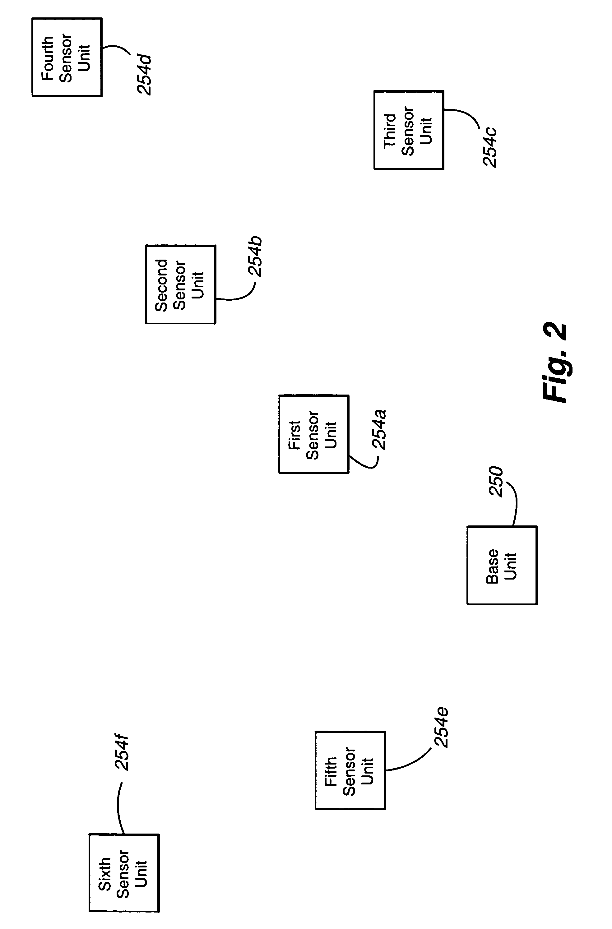
[0009](b) a base unit in communication with the sensor units and configured to operate in a network discovery mode (in which network topology information is collected) and a data polling mode (in which sensed information is collected from selected sensor units). The base unit and sensor units are spatially dispersed in different locations. Each of the sensor units is at least partially deactivated or in sleep mode until (i) a signal is received by the sensor unit from the base unit and / or the arrival of a scheduled time (which is received from the base unit) to perform a specified activity. As used herein, “sleep” mode means a self-deactivation of a sensor or control unit until a predetermined time or receipt of a predetermined signal and / or a reduction in electrical activity or circuit function below a selected threshold (which typically is a cumulative current drawn from the available (e.g., on board) power source of no more than about 5% of that drawn during the “wake” mode). More typically, the cumulative current is no more than about 1 mA in any measured period. “Wake” mode, in contrast, means an operational state when the sensor or control unit is activated, such as upon self-activation of the sensor or control unit at a predetermined time or upon receipt of a predetermined signal. Because the sensor units are activated on an “as needed” basis, the operational life of the stored primary power supply of each sensor unit is substantially lengthened.
[0031]The anemometer includes a controller operable (i) during a first time interval, to transmit a first measurement (e.g., ultrasonic) signal from the first transducer to the second transducer; (ii) during a subsequent second time interval, to transmit a second measurement signal from the second transducer to the first transducer; (iii) during a subsequent third time interval, to transmit a third measurement signal from the third transducer to the fourth transducer; and (iv) during a subsequent fourth time interval, to transmit a fourth measurement signal from the fourth transducer to the third transducer. To provide inexpensive and sensitive circuitry, the first, second, third, and fourth transducers are multiplexed together to use a common receive circuit, though the transducers have separate transmit circuits.
[0036](d) a second conduit in communication with the outlet. Adjacent ends of the first and second conduits are spaced from one another. To provide accurate and repeatable droplet counts, the adjacent ends of the first and second conduits are angled relative to a selected horizontal plane and / or the second conduit comprises a longitudinal slot extending downwardly from the end of the second conduit.
[0037]The various embodiments can have advantages relative to existing systems. First, the sensor units can be mounted permanently at key locations to collect real-time information for use in atmospheric / plume models to establish atmospheric baseline dispersion patterns. Second, the sensor units can incorporate a sensor suite capable of detecting pre-event indicators (such as elevated radiation levels) with the goal of prevention of a release. Third, the sensor units can be rapidly deployable, either manually or remotely, to augment an existing SAMS network on a much finer grid in the case of an event or release. Fourth, the total cost of a SAMS using the sensor units can be relatively low, thereby enabling federal, state, and local authorities and other entities with limited budgets to implement a SAMS as part of an emergency response plan. The sensor networks can be extremely versatile and expandable with the end-user being able to mix and match sensors at each installation. This versatility permits a range of scenarios to be accommodated. Redundant communication options along with a self-configuring and self-healing network are important because a terrorist attack may well include attempts to disrupt communications and power in the target location.

Problems solved by technology

Policing emissions often requires continual monitoring of the environment for unlawful emission levels.

Method used


Image

  • Geographically distributed environmental sensor system
  • Geographically distributed environmental sensor system
  • Geographically distributed environmental sensor system

Examples


Embodiment Construction

Overview of the Networked Sensor Units

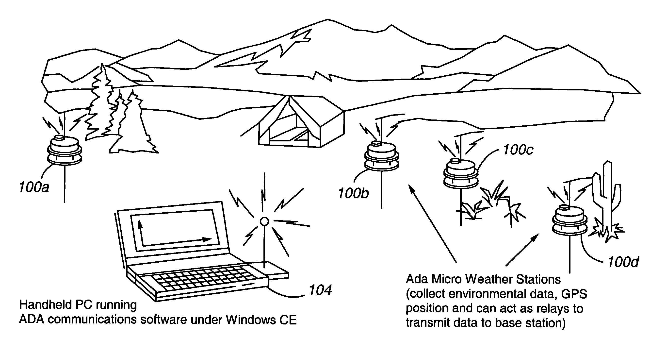
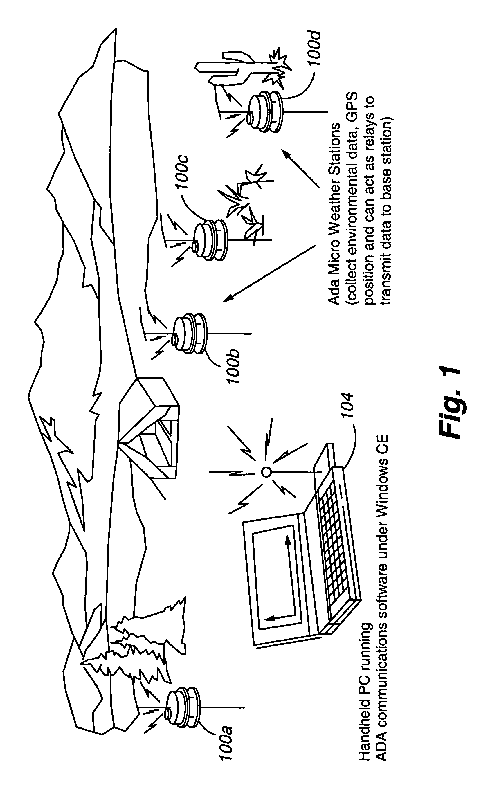
[0064]Referring to FIG. 1, the wireless networking of a plurality of sensor units is depicted. Each of the sensor units or nodes 100a–d and the base unit 104 are geographically dislocated, or dispersed over a wide area, but in wireless communication with one or more adjacent, neighboring nodes / sensor units. The various sensor units communicate with one another to exchange network topology information, control signals, and weather (e.g., humidity, rainfall levels, wind velocity and direction, radiant temperature, barometric pressure, and air temperature, and other measurement information.

[0065]The units may be deployed by numerous techniques. For example, they can be employed manually or automatically, such as by airborne delivery systems.

[0066]The sensor units can wirelessly communicate using analog or digital signals over any suitable carrier frequency range, such as the RF, microwave, and millimeter frequency spectra. A particularly preferred ...


PUM


Abstract

The present invention is directed to a sensor network that includes a number of sensor units and a base unit. The base station operates in a network discovery mode (in which network topology information is collected) in a data polling mode (in which sensed information is collected from selected sensory units). Each of the sensor units can include a number of features, including an anemometer, a rain gauge, a compass, a GPS receiver, a barometric pressure sensor, an air temperature sensor, a humidity sensor, a level, and a radiant temperature sensor.

Description

CROSS REFERENCE TO RELATED APPLICATIONS[0001]The present application claims priority from U.S. Provisional Application Ser. No. 60 / 464,495, filed Apr. 21, 2003, entitled “GEOGRAPHICALLY DISTRIBUTED ENVIRONMENTAL SENSOR SYSTEM”, which is incorporated herein by this reference.STATEMENT REGARDING FEDERALLY SPONSORED RESEARCH OR DEVELOPMENT[0002]The U.S. Government has a paid-up license in this invention and the right in limited circumstances to require the patent owner to license others on reasonable terms as provided for by the terms of Contract No. DOD DAMD 17-00-C0010 and DOD NAVC N00164-02-C-6007 both awarded by the U.S. Department of Defense and Contract No. DE-FG02-03ER 83590 awarded by the Department of Energy.FIELD OF THE INVENTION[0003]The present invention relates generally to environmental sensing devices and specifically to networked environmental sensing devices.BACKGROUND OF THE INVENTION[0004]Monitoring of environmental conditions is becoming an increasingly important ac...

Claims


Application Information

Patent Timeline
IPC IPC(8): G01W1/00
CPCG01W1/00G01W1/02
Inventor FRENCH, PATRICKVEATCH, BRADO'CONNOR, MIKE
Owner ADVANCED DISTRIBUTED SENSOR SYST
Learn More