Eureka AIR delivers breakthrough ideas for toughest innovation challenges, trusted by R&D personnel around the world.

Apparatus for high resolution imaging of moving organs

a tomographic apparatus and high-resolution technology, applied in the field of optical coherence tomographic apparatus, can solve the problems of oct transversal images showing only fragments of the retina, difficult to interpret, and loss of absolute depth of individual images in the stack, and achieving a proportionately lower strength of oct signals

Inactive Publication Date: 2006-09-26
OPTOS PLC
View PDF23 Cites 52 Cited by
  • Summary
  • Abstract
  • Description
  • Claims
  • Application Information

AI Technical Summary

Benefits of technology

[0021]There is a transverse scanning means to effect transverse scanning of the beam; an interferometer in the respective optical coherence tomography imaging instrument; depth adjustment means comprising electronically controllable optical path altering means for altering the optical path difference in the interferometer; and interface optics for transferring an optical beam from

Problems solved by technology

These papers also demonstrate that, owing to the low coherence length, the OCT transversal images show only fragments of the retina and are difficult to interpret.
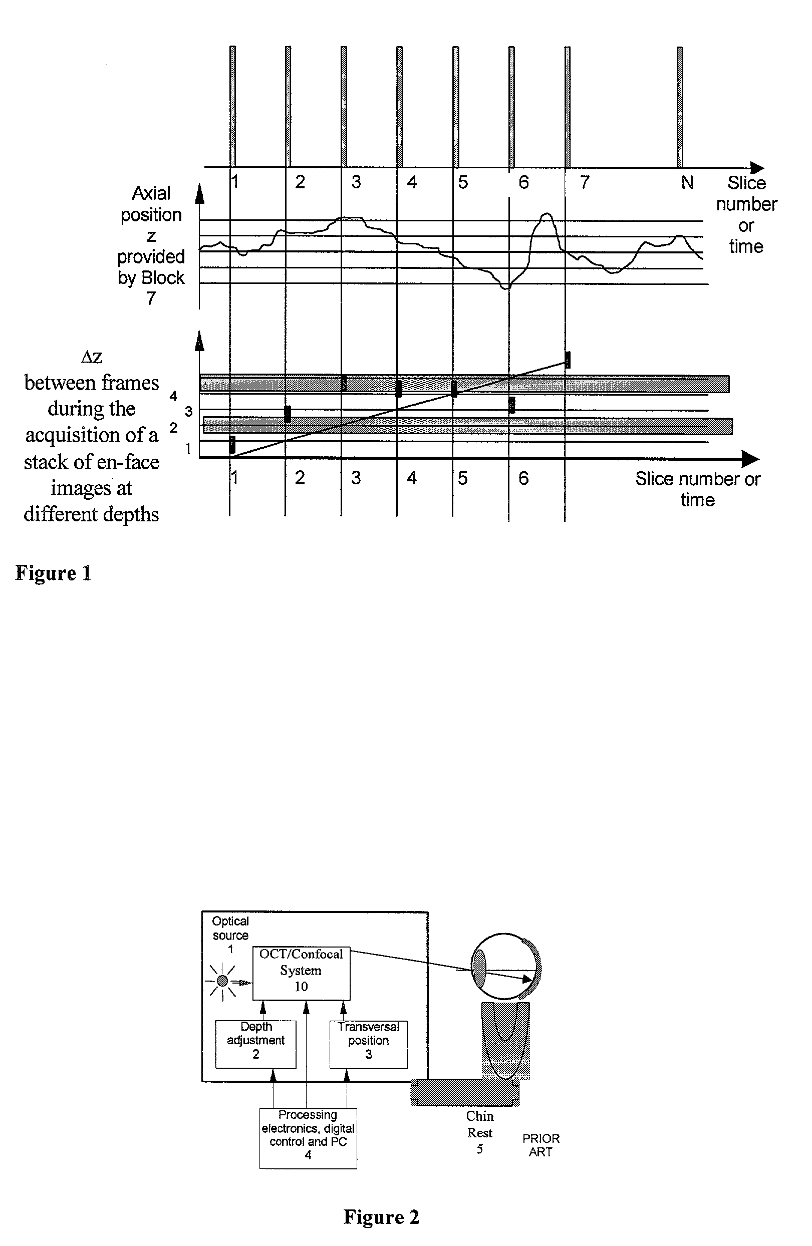
However, due to the inadvertent axial movement of the eye during investigation, the absolute depth of the individual images in the stack loses precision.
This results in a proportionately lower strength for the OCT signal than when using a mirror.
It is practically impossible to establish the correspondence of these peaks to layers in the cornea and retina.
(iv) The main disadvantage of the method lies in the poor signal to noise ratio, as both interfering signals come from the target and have relatively low amplitudes.
This complicates the set-up and reduces the S / N ratio even further.
The fourth Purkinje reflection is weak, as it comes from the posterior surface of the lens and as another disadvantage, such eye trackers are not sensitive to the axial eye movements.
However, all these solutions require extra devices and the measuring error may not be at the level required by the high resolution imaging instrument.
Apart from being insensitive to the axial movement, the attachment of tiny reflectors to the eye is not applicable to all eyes and the reflector requires sterilisation or to be devised as for single usage.

Method used


Image

  • Apparatus for high resolution imaging of moving organs
  • Apparatus for high resolution imaging of moving organs
  • Apparatus for high resolution imaging of moving organs

Examples


first embodiment

[0121]FIG. 4a shows, in diagrammatic form, an (ophthalmic) apparatus 100 in accordance with the present invention. As shown in FIGS. 4a and 4b, the apparatus 100 comprises in addition to the elements in FIG. 2, a splitting element, 6, which allows the common axis of the light to the eye to be shared by the OCT or the OCT / confocal system, 10, and the axial position sensing block, 7a. The axial position of the organ (cornea in the case of the eye) is read by the block 7 and fed into the processing electronics and digital control system, 4. The apparatus according to the invention is also equipped with processing procedures to acquire stacks of images stored in the memory of the control system, 4. A block for error indication 8, informs the user using visual and audio stimuli about the state of the system while acquiring slices under the control of the block 4.

[0122]FIG. 4b is similar to FIG. 4a, except that it also shows a second transverse position sensing device 7b. In this case, th...

second embodiment

[0153]FIGS. 11a,b,c show the splitting element where the OCT beam and the beam of the sensing block of the axial—and eventually of the transverse—position 7a and 7b, respectively, share a beam-splitter, 6. If the sensing block of the axial position, 7a, uses optical waves of similar wavelength with that of OCT, then the beam-splitter ratio is chosen as such as the transmission of the OCT signal (when working in transmission) or the reflection of the OCT signal (when working in reflection) to be as high as possible. The beam-splitter 6 can be a cold mirror, a hot mirror, or and edge filter, which is used to transmit wavelengths from one band and reflect wavelengths from a different band. When the beam-splitter 6 is a cold mirror, this may be used for instance to transmit wavelengths larger than 1000 nm, a band used by the OCT / confocal imaging system, 10, and reflects wavelengths smaller than 1000 nm, in a band used by the sensing blocks 7a and 7b. This case is illustrated in FIG. 11a...


PUM


Abstract

Apparatus for high resolution imaging of a moving object comprises a source of low coherence light, an optical coherence tomography imaging instrument or a dual channel, optical coherence tomography / confocal imaging instrument, a transverse scanner, an interferometer, depth adjustment means, and interface optics. First and an optional second sensing blocks sense the axial and respectively the transverse position of the object. A splitting element is shared so that the interface optics and the sensing blocks have a common axis of light transmitted to and from the object. Timing means establishes a timing, and timing intervals and reference times for images as they are taken. The acceptability of each scanned image is determined according to predetermined criteria. A series of en-face OCT images, or of longitudinal OCT images of the object may be taken at different depths or transverse coordinates, and the stack of collected images is used to build 3D profiles of the object.

Description

FIELD OF THE INVENTION[0001]The present invention relates to an optical coherence tomographic apparatus which can be used to provide images from moving objects such as human organs, with low sensitivity to the axial and transverse movements of the objects being scanned.[0002]The description which follows refers mainly to the eye as the object. However, this will be understood as merely exemplary, and not as a restriction of the application of the present invention. Where “eye” is mentioned, a more general transparent and scattering object or organ may be considered as well to be the scanned object.DESCRIPTION OF THE PRIOR ART[0003]High depth resolution imaging of the eye fundus can be achieved by optical coherence tomography (OCT) as shown in the paper “Optical coherence tomography” by D. Huang, E. A. Swanson, C. P. Lin, J. S. Schuman, W. G. Stinson, W. Chang, M. R. Hee, T. Flotte, K. Gregory, C. A. Puliafito and J. G. Fujimoto, Science 254, (1991). pp. 1178 and in the paper “Optica...

Claims


Application Information

Patent Timeline
IPC IPC(8): A61B6/00A61B3/12G01B9/02
CPCA61B3/102A61B3/1025G01B9/0203G01B9/02077G01B9/02083G01B9/02091G01B2290/65
Inventor PODOLEANU, ADRIANROGERS, JOHN
Owner OPTOS PLC
Why Eureka
Eureka Blog
Learn More