Atomic force microscope

a microscope and microscope technology, applied in the field ofatomic force microscopes, can solve the problems of low-frequency oscillation of the floor, environmental noise, limiting the upper scanning speed and/or depth resolution obtainable with an afm, etc., and achieves less shielding, less sensitivity to low-frequency environmental noise, and suppress the impact of low-frequency electrical and mechanical noise.

Active Publication Date: 2006-09-26
ALCATEL-LUCENT USA INC
View PDF13 Cites 18 Cited by
  • Summary
  • Abstract
  • Description
  • Claims
  • Application Information

AI Technical Summary

Benefits of technology

[0007]Various embodiments provide atomic force microscopes (AFMs) that are less sensitivity to the low-frequency environmental noise. The AFMs have both cantilever and sample stage feedback controllers. The feedback controllers are connected in a parallel configuration so that both controllers receive a voltage signal indicative of the error in the force that the sample exerts on the cantilever. The parallel configuration suppresses the impact of low-frequency electrical and mechanical noise on the sample stage more effectively than typical nested feedback configurations. In particular, the parallel configuration reduces the excitation of resonant mechanical vibration modes in the sample stage at low frequencies associated with building and acoustic noise. Thus, it may be possible to use less shielding for low-frequency environmental noise and thus, provide more accessible AFM setups.

Problems solved by technology

One source of such noise is low-frequency oscillations of the floor in the room where the AFM is set up, i.e., building noise.
In many cases, environmental noise limits the upper scanning speed and / or the depth resolution obtainable with an AFM.

Method used


Image

  • Atomic force microscope
  • Atomic force microscope
  • Atomic force microscope

Examples


Embodiment Construction

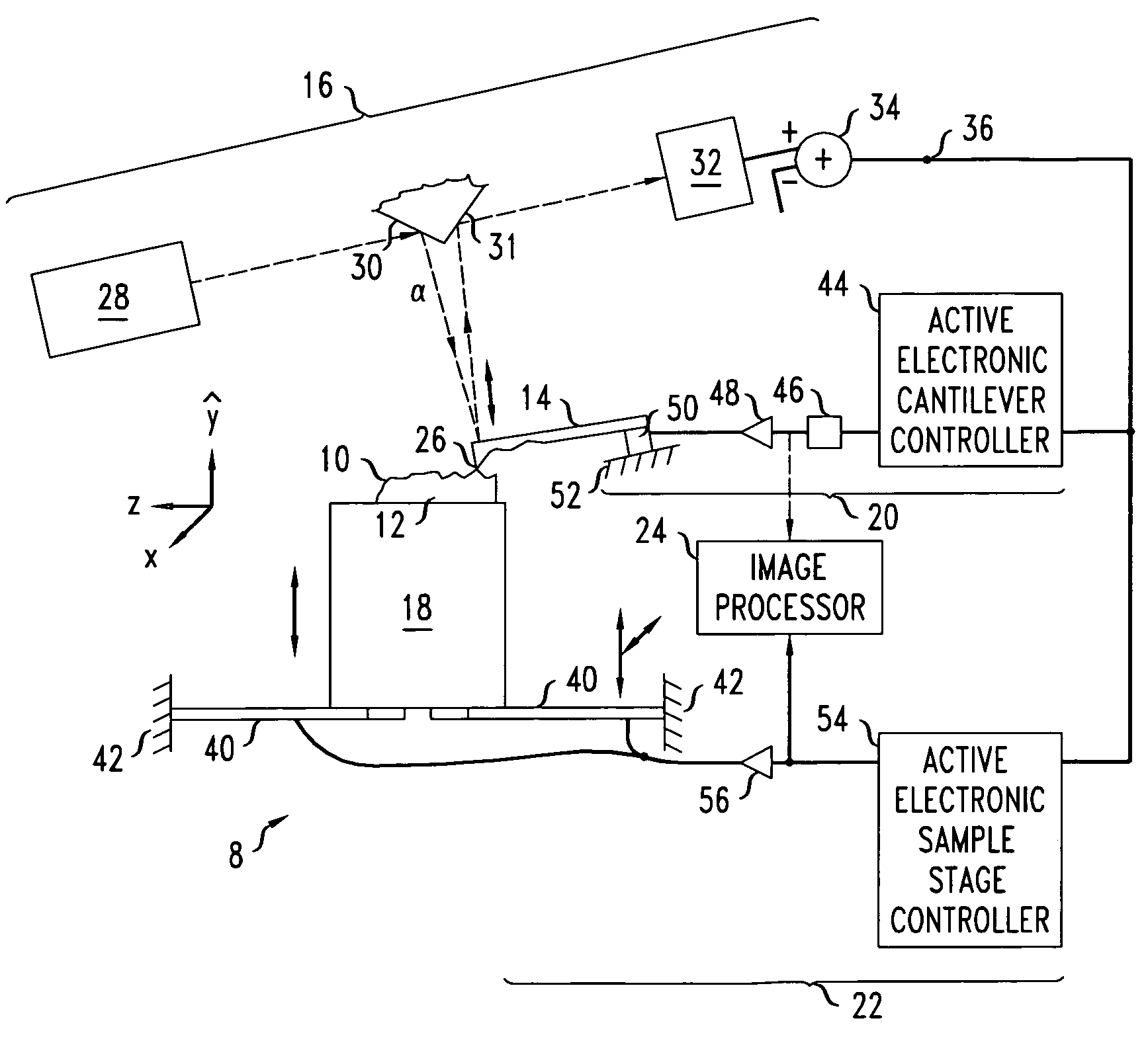
[0021]FIG. 1 illustrates an AFM 8 that is configured to image surface 10 of sample 12. The AFM 8 includes a flexible mechanical cantilever 14, a cantilever-force detection system 16, a sample stage 18, an active cantilever feedback system 20, an active sample stage feedback system 22, and an image processor 24.

[0022]The mechanical cantilever 14 includes a fine tip 26. During a scan, the fine tip 26 either is in contact with the sample surface 10 or oscillates over the surface 10, e.g., to regularly tap the surface 10. During both the contact and oscillatory modes of scanning, the surface 10 of the sample 12 exerts a vertical force on the tip 26, i.e., along the ŷ-direction, and thus, exerts a vertical force on the free end of the mechanical cantilever 14. In the contact mode of scanning, the vertical force affects the amount of bending of the mechanical cantilever 14. In the oscillatory mode of scanning, the vertical force exerted by the surface 10 on the tip 26 affects the oscillat...


PUM

PropertyMeasurementUnit
frequencyaaaaaaaaaa
voltagesaaaaaaaaaa
cantilever-force erroraaaaaaaaaa

Abstract

An apparatus includes a sample stage, a cantilever mount, a cantilever-force detector, a cantilever feedback system, and a sample stage feedback system. The sample stage is configured for holding a sample. The cantilever mount is configured for mechanically fixing a mechanical cantilever having a scanning tip. The cantilever-force detector is configured to produce an electrical cantilever-force error signal. The cantilever feedback system is configured to electromechanically drive the mechanical cantilever in a manner responsive to the cantilever-force error signal. The sample stage feedback system is configured to electromechanically displace the sample stage in a manner responsive to the cantilever-force error signal. The cantilever feedback system and the sample stage feedback system are connected to receive the cantilever-force error signal in parallel.

Description

BACKGROUND[0001]1. Field of the Invention[0002]The invention relates to atomic force microscopes and methods of operating atomic force microscopes.[0003]2. Discussion of the Related Art[0004]An atomic force microscope (AFM) is a high-resolution device for producing scanned images of the surfaces of samples. One type of AFM has a flexible cantilever with a narrow tip, a deflection detector, a sample stage, and cantilever and sample stage feedback / drive systems. The AFM produces an image by mechanically scanning the cantilever's tip over a surface of a sample. During scanning, the deflection detector measures the amount of cantilever bending. The amount of bending is related to the vertical force that the sample exerts on the cantilever's tip, i.e., the sample-cantilever force. During the scanning, the feedback / drive systems produce movements for restoring this sample-cantilever force to an initial state. The AFM produces a topographical image of the sample's surface by recording the ...

Claims


Application Information

Patent Timeline
Patent Type & Authority Patents(United States)
IPC IPC(8): G01B5/28G01N13/16G01Q10/06
CPCB82Y35/00G01Q20/02G01Q10/065
Inventor BLUMBERG, GIRSHSCHLOCKERMANN, CARL JOHANNES
Owner ALCATEL-LUCENT USA INC
Why Eureka
Try Eureka