Chain tensioner

Inactive Publication Date: 2006-09-19
INA WALZLAGER SCHAEFFLER KG
View PDF11 Cites 19 Cited by
  • Summary
  • Abstract
  • Description
  • Claims
  • Application Information

AI Technical Summary

Benefits of technology

[0007]According to one aspect of the present invention, a chain tensioner includes a tensioner piston bearing upon a chain; a cylinder guiding the piston for movement in a direction of the chain and bounding with the piston a pressure chamber for receiving hydraulic fluid; a leakage gap for migration of hydraulic fluid from the pressure chamber; and a control member for at least reducing the leakage gap in size, when a pressure in the pressure chamber increases.
[0008]The present invention resolves prior art problems by providing a control member to at least reduce the leakage gap with increasing pressure in the pressure chamber. This size reduction of the leakage gap includes also the possibility of a complete closing in situations, when this leakage gap is provided in addition to another leakage gap. As a result of the size adjustment of the leakage gap, the characteristic damping curve of the chain tensioner is dependent on the pressure in the pressure chamber and also dependent on the motor speed. In a lower speed range and thus lower fluid pressure in the pressure chamber, the leakage gap expands, which means that the chain tensioner has a soft characteristic damping curve. In a higher speed range and thus greater fluid pressure in the pressure chamber, the leakage gap is smaller, which means that the chain tensioners exhibits a harder characteristic damping curve. In this way, the chain tensioner according to the present invention is best suited to meet the desires of automobile manufactures, namely to provide a chain tensioner that exhibits a characteristic damping curve that varies in response to the motor speed.

Problems solved by technology

This size reduction of the leakage gap includes also the possibility of a complete closing in situations, when this leakage gap is provided in addition to another leakage gap.
An outward movement of the piston in the direction toward the chain results in a volume expansion of the pressure chamber so that a negative pressure is generated in the pressure chamber, causing an opening of the check valve.

Method used


Image

  • Chain tensioner
  • Chain tensioner

Examples


Embodiment Construction

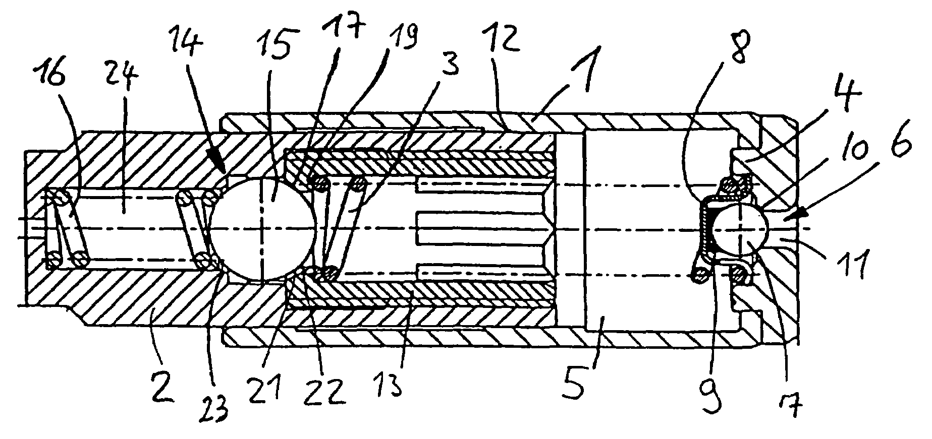
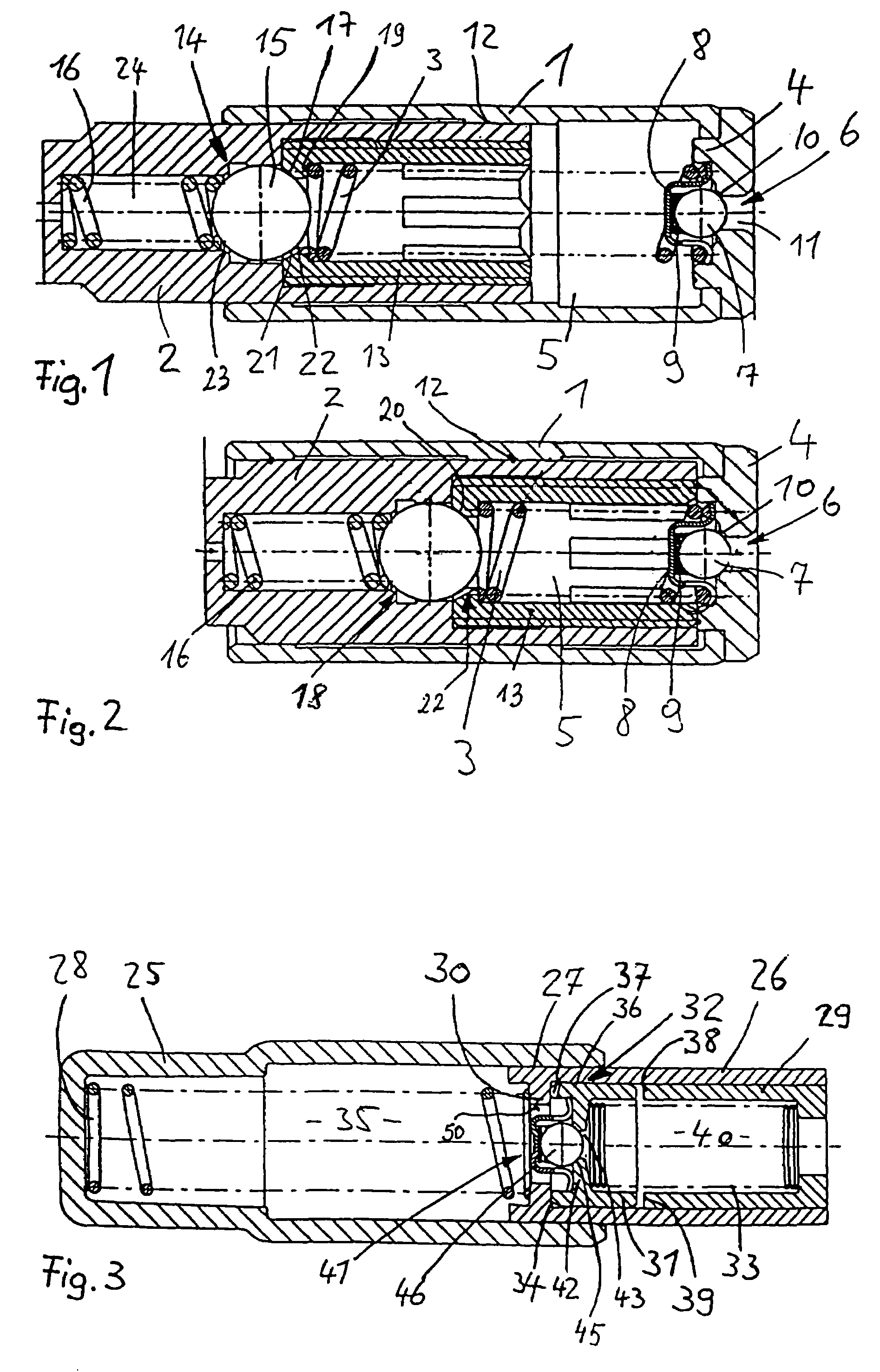
[0025]Turning now to the drawing, and in particular to FIG. 1, there is shown a longitudinal section of one embodiment of a chain tensioner according to the present invention, attached to a, not shown, cylinder head (or engine block) of an internal combustion engine, for keeping a power transmitting member (not shown), such as a chain of a chain drive in a tensioned state.

[0026]It is to be understood that the principles described in the following description with respect to a chain tensioner are generally applicable to any other type of tensioner which generally follows the concepts outlined here. For convenience and sake of simplicity, FIG. 1 and the following description refer only to those areas of the chain tensioner that form part of the present invention and are necessary for the understanding.

[0027]The chain tensioner includes a cylinder 1 and a tensioner piston 2, which is received in the cylinder 1 for axial displacement in the direction of the chain. The cylinder 1 has a b...


PUM


Abstract

A tensioner for a chain, includes a tensioner piston bearing upon a chain and guided by a cylinder for movement in the direction of the chain. The cylinder and the piston define a pressure chamber for receiving hydraulic fluid, wherein hydraulic fluid is able to escape from the pressure chamber via a leakage gap. A control member is provided to at least reduce the leakage gap in size, when a pressure in the pressure chamber increases.

Description

CROSS-REFERENCES TO RELATED APPLICATIONS[0001]This application claims the priority of German Patent Application Serial No. 100 38 606.7, filed Aug. 8, 2000, the subject matter of which is incorporated herein by reference.BACKGROUND OF THE INVENTION[0002]The present invention relates, in general, to a tensioner, and more particularly to a chain tensioner as used in chain drives of internal combustion engines for tensioning the chain during operation.[0003]German Pat. No. DE 40 35 823 C1 describes a hydraulic tensioner for traction drives, in particular chain drives in internal combustion engines. A tensioner piston is pressed against the chain and received in a cylinder for longitudinal displacement. The piston and the cylinder together define a pressure chamber for hydraulic fluid. As the piston moves in the direction of the chain to tension it, the pressure chamber expands, thereby creating a negative pressure. As a consequence, a check valve opens and motor oil is able to flow int...

Claims


Application Information

Patent Timeline
IPC IPC(8): F16H7/08
CPCF16H7/0836F16H2007/0806F16H2007/0859F16H2007/0814F16H2007/0812
Inventor ULLEIN, THOMASSCHUSEIL, BOLKO
Owner INA WALZLAGER SCHAEFFLER KG
Why Eureka
Try Eureka