
Control method for an exhaust gas purification system and an exhaust gas purification system

a technology of exhaust gas purification system and control method, which is applied in the direction of electrical control, exhaust treatment electric control, separation process, etc., can solve the problems of increasing exhaust gas pressure as a result of filter clogging, increasing engine load, and increasing exhaust gas pressure, so as to promote the regeneration of dpf and improve the efficiency of self-regeneration of dpf , the effect of increasing the engine load

Inactive Publication Date: 2006-09-12
ISUZU MOTORS LTD
View PDF13 Cites 59 Cited by
  • Summary
  • Abstract
  • Description
  • Claims
  • Application Information

AI Technical Summary

Benefits of technology

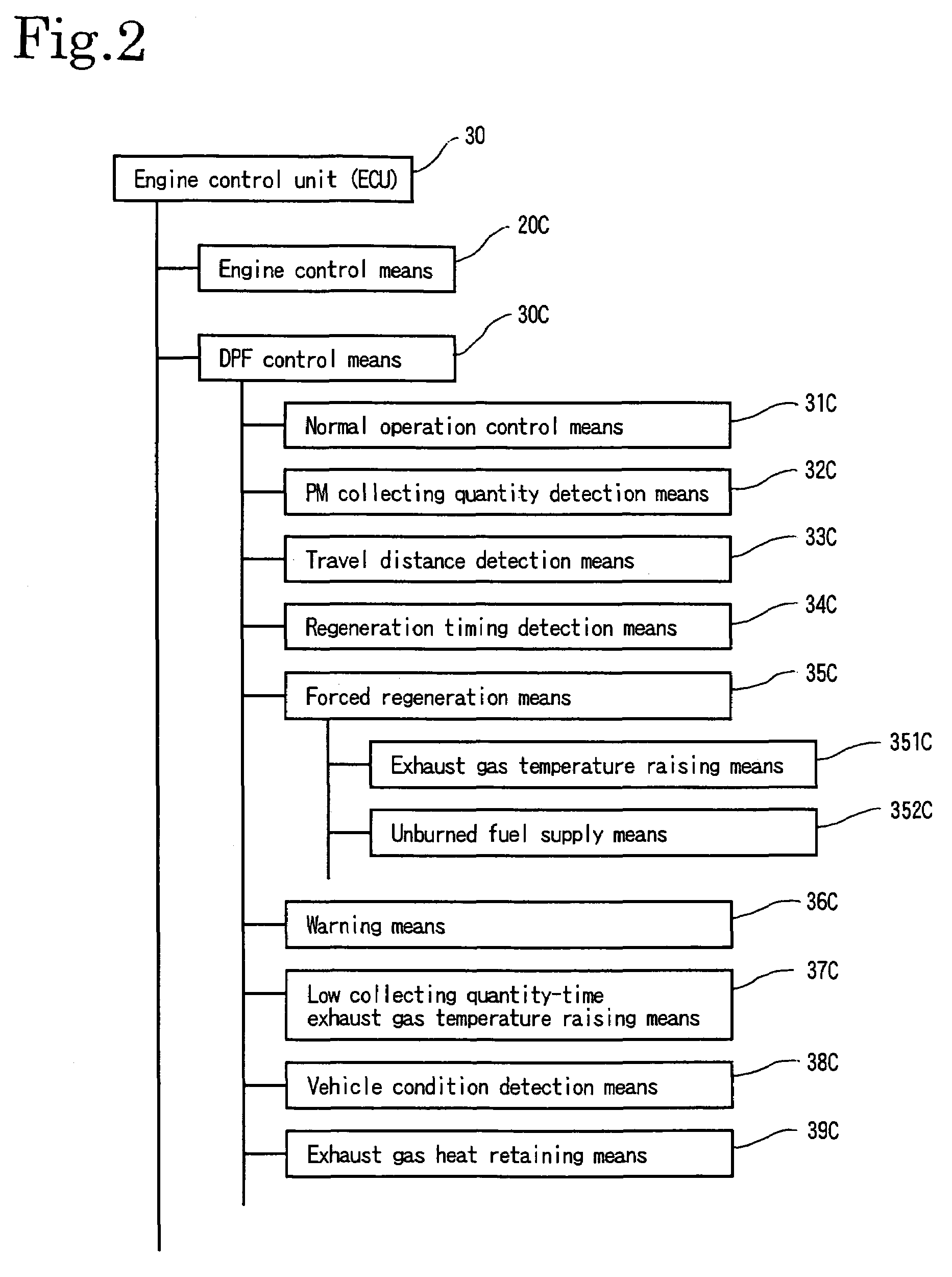
The present invention provides a control method for an exhaust gas purification system in vehicles that includes a continuous regeneration DPF device and an exhaust throttle valve. The control method includes a DPF control means that detects the quantity of collected matters in the DPF device and the vehicle's travel distance. The control means automatically initiates a regeneration during traveling and a manual regeneration control for low collecting quantity-time. The system also includes an exhaust gas temperature raising means for raising the exhaust gas temperature and a low collecting quantity-time exhaust gas temperature raising means for controlling the vehicle's speed. The control method improves the efficiency of exhaust gas purification and ensures effective burning of collected matters even during low-collecting quantity-time. The system can also detect the stationary and traveling conditions of the vehicle and adjust the regeneration timing accordingly.

Problems solved by technology

However, even in continuous regeneration DPF devices, increasing exhaust gas pressure as a result of filter clogging has become a problem.
Accordingly, the accumulation of PM in the filter continues and clogging thereof is accelerated.
In terms of oil dilution, it is undesirable that forced regenerating processing be too frequently carried out.
If forced regenerating processing is carried out while the vehicle is being traveled, the engine speed will be high in comparison with that of stationary idling; accordingly, it is inevitable that post injection volume increases with a result that the degree of diluting of oil by fuel increases.
In particular, a post injection control becomes difficult during transient condition.
In other words, even if the engine temperature is raised in a transient condition resulting from load variation, post injection is performed wastefully.
It is difficult to avoid this type of wasteful injection.
And furthermore, if left unaddressed, oil dilution can lead to the problems of excessive wear or scorching of the moving mechanical components.
Furthermore, since a vehicle has a wide range of traveling patterns, problematic clogging unrelated to differential pressure and resulting from uneven loading of PM can also occur.
However, PM does not accumulate at the center of the filter, and uneven accumulating—in other words, accumulation in a circular pattern around the outside thereof—occurs.
As a result, extremely high temperatures occur within the interior of the filter.
And this runaway burn is a cause of the DPF melting.
Furthermore, in the case of vehicles often driven by low-speed / high-load traveling patterns, flashing of the lamp to notify the driver the need of manual regeneration is so frequent that the driver feels it troublesome.
This repetition makes engine load varies between traveling condition and stationary idling condition in a complicated manner.
Consequently, the exhaust gas temperature also varies in a complicated manner.
Furthermore, since the engine load in stationary idling is low, the combustion condition upon multi injection is not stable when low collecting quantity-time exhaust gas temperature raising control continues to be active, and as a result, exhaust gas temperature raising is not possible.
For this reason, different traveling patterns can cause problems such that unburned fuel ultimately turns into white smoke to be discharged to the atmosphere and fuel efficiency deteriorates.
That is to say, it is possible that DPF regenerating control will not terminate within the preset time, that it will not be possible to sufficiently raise the exhaust gas temperature, and that the collected PM will not be burned and removed sufficiently.
Furthermore, since the combustion condition is not stable, not all of the injected fuel is burned within each cylinder, and in addition, since the exhaust gas temperature is low, this unburned fuel is not oxidized by the action of the oxidation catalyst and flows therefrom into exhaust duct can occur.
In addition, as the exhaust gas temperature drops while the vehicle is in the stationary idling condition, even when traveling thereof restarts, a certain period of time is required until the exhaust gas temperature is raised to where self-regeneration of the DPF is accelerated, the time required for execution of low collecting quantity-time exhaust gas temperature raising control using multi injection becomes longer, and this causes a problem of impaired fuel efficiency.

Method used


Image

  • Control method for an exhaust gas purification system and an exhaust gas purification system
  • Control method for an exhaust gas purification system and an exhaust gas purification system
  • Control method for an exhaust gas purification system and an exhaust gas purification system

Examples


Embodiment Construction

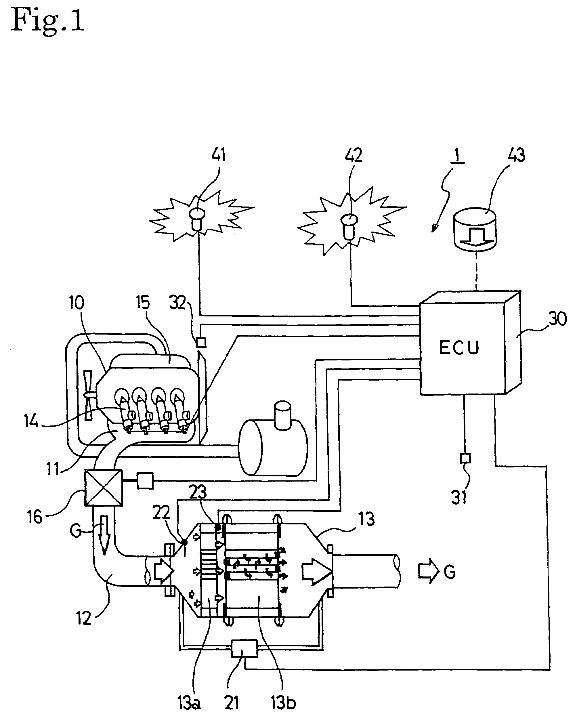
[0036]Hereinafter, the preferred embodiments of the control method for an exhaust gas purification system and the exhaust gas purification system according to the present invention will be described with reference to the accompanying drawings. The following explanation will use the example of an exhaust gas purification system provided with a continuous regeneration-type diesel particulate filter (DPF) device comprising a combination of an oxidation catalyst and a filter with a catalyst.

[0037][Configuration of Exhaust Gas Purifying System]

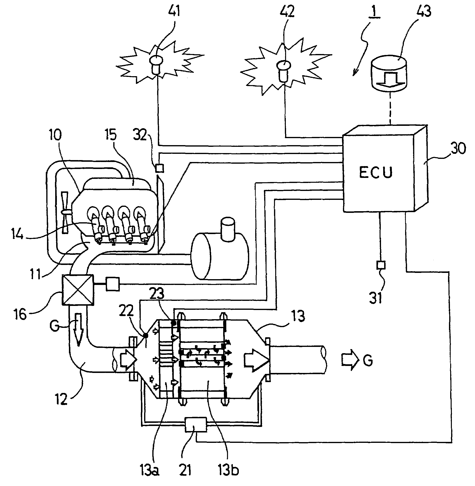
[0038]FIG. 1 shows the configuration of an exhaust gas purification system 1 for an internal combustion engine according to an embodiment of the present invention. This exhaust gas purification system 1 is configured to provide a continuous regeneration DPF device 13 and an exhaust throttle valve 16 on an exhaust passage 12 connected to an exhaust manifold 11 of a diesel engine 10. This continuous regeneration DPF device 13 is configured with an ox...


PUM

PropertyMeasurementUnit
temperatureaaaaaaaaaa
travel distanceaaaaaaaaaa
exhaust gas temperatureaaaaaaaaaa

Abstract

A method and system providing a vehicle condition detection means (38C) for detecting the stopped and traveling state of a vehicle, and when the vehicle condition detection means (38C) detects that the vehicle has stopped during operation of an exhaust gas temperature raising means (351C), closing an exhaust gas throttling valve (16) in addition to continuing the operation of the exhaust gas temperature raising means (351C), and subsequently, when the vehicle's traveling state is detected, opening the exhaust gas throttling valve (16) and continuing the operation of the exhaust gas temperature raising means (351C). Accordingly, in terms of the regeneration of a continuous regeneration-type DPF device (13) capable of significantly reducing the frequency with which the driver is urged to stop the vehicle and perform forced regeneration, the exhaust gas can be efficiently maintained at a high temperature, and reliable burning of PM is possible even for driving patterns featuring frequent waiting at traffic signals in urban areas, even upon transition to the stationary idling condition during automatic traveling regeneration.

Description

BACKGROUND OF THE INVENTION[0001]The present invention relates to an exhaust gas purification system that purifies particulate matters (PM) from the exhaust gas discharged by diesel and other internal combustion engines using a continuous regeneration-type diesel particulate filter (DPF) and also to a control method thereof.[0002]In the same way as for NOx, CO, and also HC etc., restrictions on the volume of particulate matters (hereinafter “PM”) discharged from diesel internal combustion engines grow severe every year. Techniques for collecting this PM in a filter known as a diesel particulate filter (hereinafter “DPF”) and for reducing the quantity thereof by discharging externally have been developed. Continuous regeneration DPF devices represent such.[0003]However, even in continuous regeneration DPF devices, increasing exhaust gas pressure as a result of filter clogging has become a problem. In other words, although the PM collected by these continuous regeneration DPF devices ...

Claims


Application Information

Patent Timeline
Patent Type & Authority Patents(United States)
IPC IPC(8): F01N3/00F02D9/04B01D46/42B01D53/94F01N3/02F01N3/023F01N3/025F01N3/029F01N3/035F01N3/18F01N3/20F01N3/24F01N9/00F01N11/00F01N13/02F02D41/02F02D41/04F02D41/38F02D41/40F02D43/00F02D45/00
CPCF01N3/0231F01N3/0235F01N3/0253F01N3/035F01N9/002F01N13/0097F02D41/029F02D41/405F02D2041/228F02D2200/501F02D2250/11Y02T10/47Y02T10/40
Inventor SATO, HITOSHIMASHIKO, TATSUOONODERA, TAKAOMATSUNUMA, ATSUSHIHASEYAMA, TAKASHIWU, WEIIWASHITA, TAKUROIKEDA, SHIGERU
Owner ISUZU MOTORS LTD
Learn More