
MCrAlY-coating

a technology of mcraly coating and mcraly coating, which is applied in the direction of wind motor components, non-positive displacement fluid engines, liquid fuel engine components, etc., can solve the problems of low aluminum content and hence low aluminum reservoir, high tmf damage, and large difference between the mechanical behavior of the single crystal substrate and the multi-crystal coating system, so as to achieve the effect of increasing oxidation resistan

Inactive Publication Date: 2006-08-22
GENERAL ELECTRIC TECH GMBH
View PDF24 Cites 40 Cited by
  • Summary
  • Abstract
  • Description
  • Claims
  • Application Information

AI Technical Summary

Benefits of technology

The present invention relates to a new coating called γ / γ′-MCrAlY-coating and a method for applying it to a single crystal article. The coating is a defect-free, epitaxial coating that has the same crystallographic orientation as the substrate. The coating has been found to have a small solidification interval and a last 5% of the liquid must solidify in a temperature interval smaller than 15° C to prevent cracking. The composition of the coating is well balanced to avoid large segregation and low melting interdendritic constituent or as close as possible to the eutectic line on the γ-phase side of the eutectic line of the ternary phase diagram Ni—Al—Cr. The coating can be applied by laser cladding and is effective in providing oxidation resistance to the article.

Problems solved by technology

However the limitations are the low aluminum content and hence their low reservoir of aluminum.
However, when this coating is applied by traditional means on the single crystal substrate, the difference in the E-modulus between oriented surface layer of the substrate and randomly oriented coating grains produce high TMF damage.
However, the system of a single crystal substrate and the multicrystal coating still has a large difference in the mechanical behavior between the substrate and the coating as any equiaxed structure possesses E-modulus much higher than those for single crystal material in direction.
It was found, in fact, that it was difficult to grown a defect free epitaxial coating with the mentioned γ / γ′ forming coating material within this document.
When using other commercially available highly oxidation resistant alloys for the laser cladding process, the single crystal microstructure can not be maintained.
Hot tearing cracks and the breakdown of single crystal solidification occur in the cladded structure, which results in the formation of undesirable equiaxed grains.

Method used


Image

  • MCrAlY-coating
  • MCrAlY-coating
  • MCrAlY-coating

Examples


Embodiment Construction

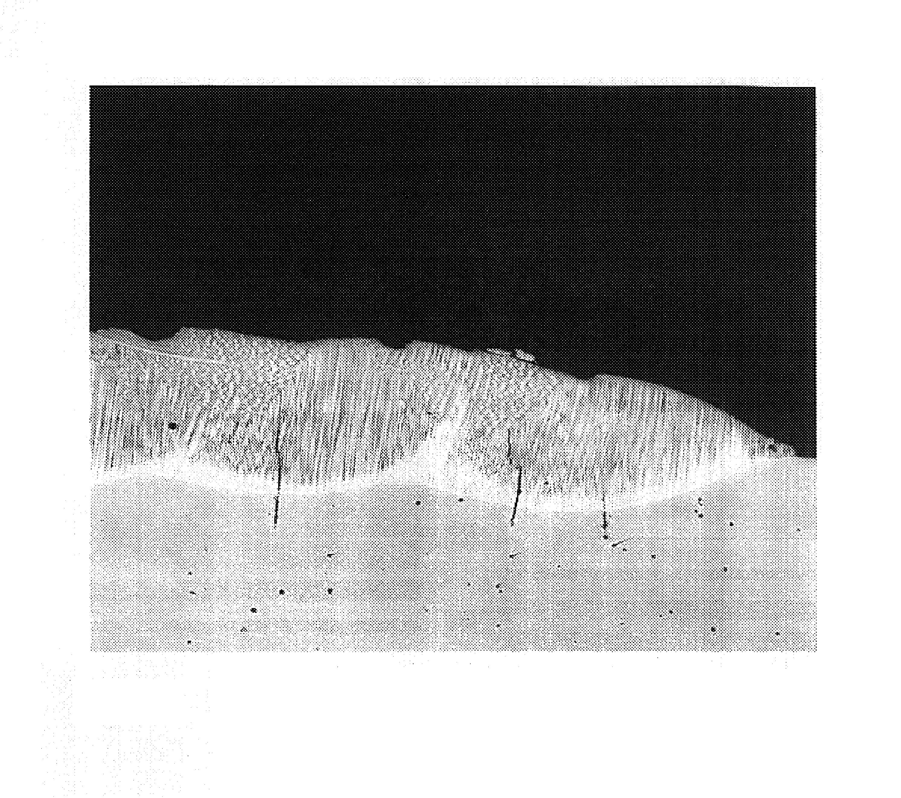
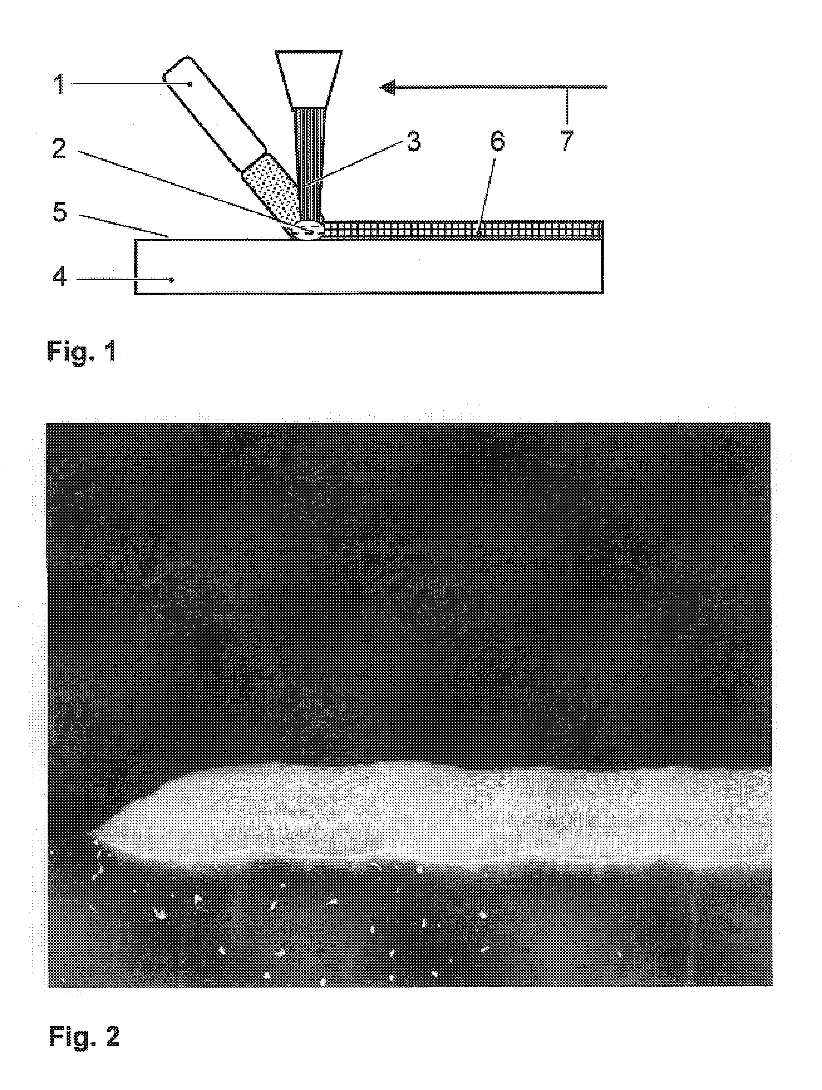
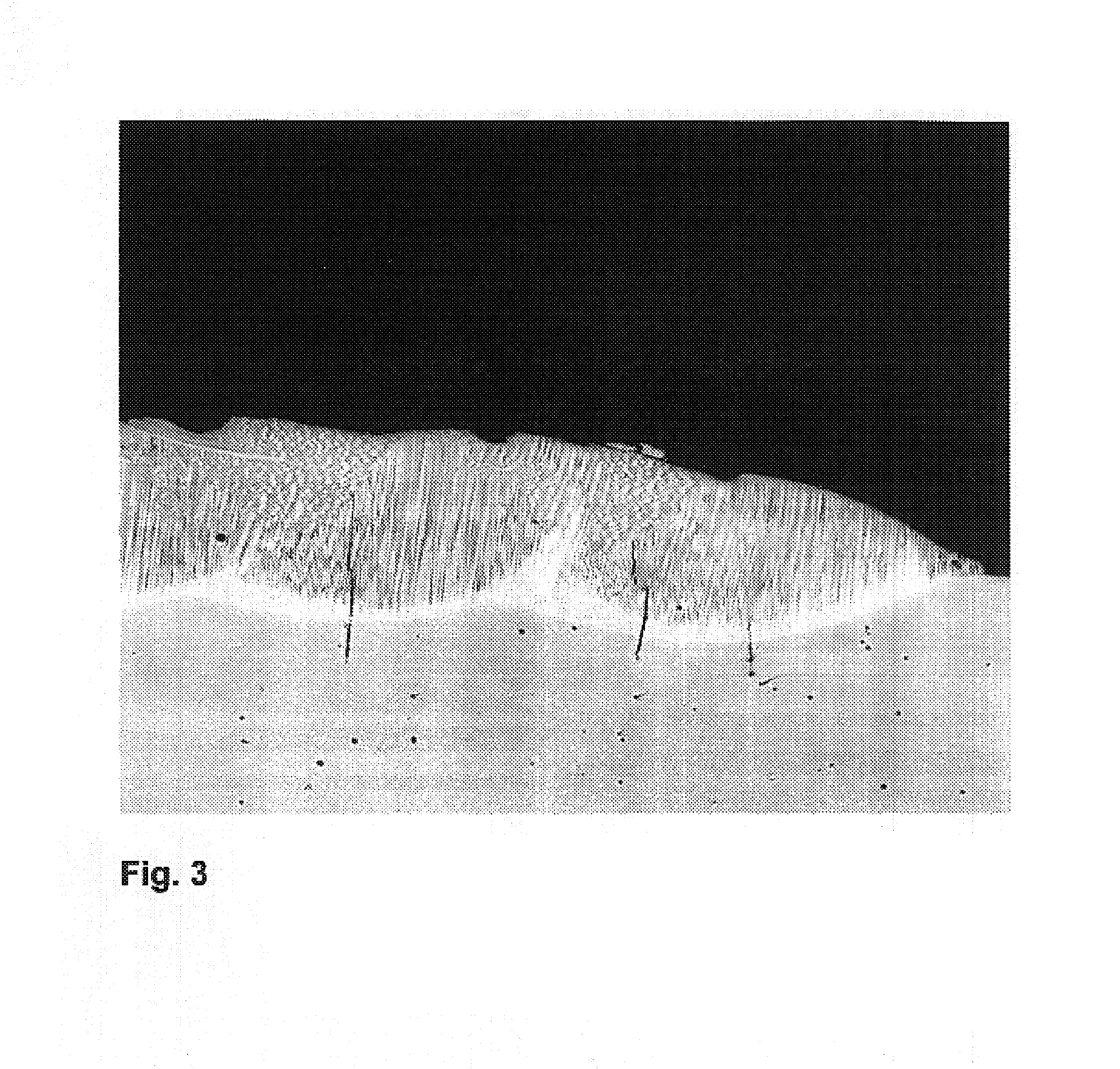
[0026]This invention is related to a method of epitaxially growing a MCrAlY-coating 6 having a γ / γ′-microstructure onto a surface 5 of an article 4 such as blades or vanes of gas turbines or any other part which is exposed to a hot temperature environment. The article 4 has a single crystal (SX) structure and can be made, as an example, from a nickel base super-alloy. Nickel base superalloys are known in the state of the art, e.g. from the document U.S. Pat. No. 5,888,451, U.S. Pat. No. 5,759,301 or from U.S. Pat. No. 4,643,782, which is known as “CMSX-4”. In general, FIG. 1 shows a laser cladding process which is characterized by impinging particles of the MCrAlY-coating material with a powder jet 1 onto a molten pool 2 formed by controlled laser heating by scanning the laser beam 3 successively over the surface 5 of the single crystal article 4. The arrow 7 shows the direction of the movement over the article 4.

[0027]The laser cladding technology has been used to apply an epitaxia...


PUM

PropertyMeasurementUnit
temperature intervalaaaaaaaaaa
thicknessaaaaaaaaaa

Abstract

A gas turbine component consists of a superalloy base material with a single crystal structure and a protective MCrAlY-coating (6). The MCrAlY-coating (6) has a g / g′ single crystal structure, which is epitaxial with the base material. It has be determined the critical factors for the successful epitaxial and crack-free growth of the MCrAlY-coating (6).

Description

FIELD OF INVENTION[0001]The invention relates to a MCrAlY-coating.STATE OF THE ART[0002]Components designed for the use in the area of high temperature, e.g. blades or vanes of a gas turbine, are usually coated with resistant coatings. The coating protects the base material against corrosion and oxidation due to the thermal effect of the hot environment and consists of an alloy mostly using the elements Al and Cr. Most turbine components are coated for the protection from oxidation and / or corrosion with, for example, a MCrAlY coating (base coat) and some are also coated with a thermal barrier coating (TBC) for thermal insulation. MCrAlY protective overlay coatings are widely known in the prior art. They are a family of high temperature coatings, wherein M is selected from one or a combination of iron, nickel and cobalt. As an example U.S. Pat. No. 3,528,861 or U.S. Pat. No. 4,585,481 are disclosing such kind of oxidation resistant coatings. U.S. Pat. No. 4,152,223 as well discloses ...

Claims


Application Information

Patent Timeline
Patent Type & Authority Patents(United States)
IPC IPC(8): B32B15/01F03B3/12F01D5/28C22C19/05C23C24/10C23C26/02C23C30/00C30B13/00C30B29/52F01D25/00F02C7/00F23R3/42
CPCC23C24/10C23C26/02C23C30/00C30B13/00C30B29/52Y10T428/12931Y10T428/12944Y10T428/12937Y10T428/12458C23C24/106
Inventor SCHNELL, ALEXANDERBEZENCON, CYRILLEHOEBEL, MATTHIASKHAN, ABDUS SUTTARKONTER, MAXIMKURZ, WILFRIED
Owner GENERAL ELECTRIC TECH GMBH
Learn More