
Ultrasound catheter calibration system

a calibration system and ultrasonic technology, applied in the field of medical catheters, can solve the problems of variations in the relative gains of coils, the inability to precisely know the distance of coils from the tip of the probe, etc., and achieve the effects of convenient electronic storage, increased procedure accuracy, and improved accuracy of position determination

Active Publication Date: 2006-08-15
BIOSENSE
View PDF36 Cites 122 Cited by
  • Summary
  • Abstract
  • Description
  • Claims
  • Application Information

AI Technical Summary

Benefits of technology

[0011]It is also an object of some aspects of the present invention to provide apparatus and methods that increase the accuracy of procedures performed with a catheter comprising a position sensor and an ultrasound transducer.
[0012]It is a further object of some aspects of the present invention to provide apparatus and methods that increase the accuracy of the determination of positions and orientations of structures imaged within the body using an ultrasound transducer affixed to a catheter.
[0013]It is yet a further object of some aspects of the present invention to provide apparatus and methods for convenient electronic storage and recall of calibration information regarding a catheter.
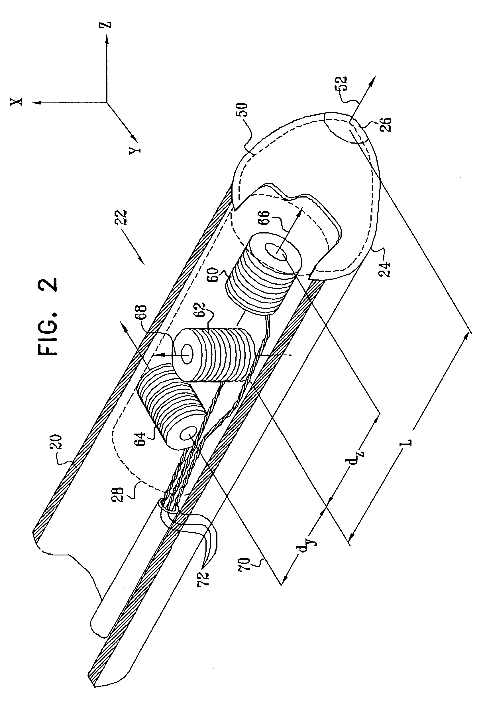
[0015]Advantageously, this calibration enables the precise registration between the ultrasound images captures by the catheter during a medical procedure and the fixed, external frame of reference in which the catheter coordinates are determined. As a result, embodiments of the present invention allow the positions and orientations of structures imaged within the body to be determined with high accuracy. In embodiments of the present invention, the orientation of the ultrasound transducer with respect to the catheter is typically calibrated to within 0.1 degrees. As a result, the position of a reconstructed pixel in an ultrasound image of a structure 5–7 centimeters away from the ultrasound transducer can be determined to within one millimeter, which represents a high level of precision.

Problems solved by technology

Because of manufacturing variations, the coils generally used in the position sensors of these position-determining systems to generate position signals may not be precisely oriented with the body of the probe.
Additionally, the distance of the coils from the tip of the probe may not be precisely known, and there may be slight variations in the relative gains of the coils in response to externally-applied fields.

Method used


Image

  • Ultrasound catheter calibration system
  • Ultrasound catheter calibration system
  • Ultrasound catheter calibration system

Examples


Embodiment Construction

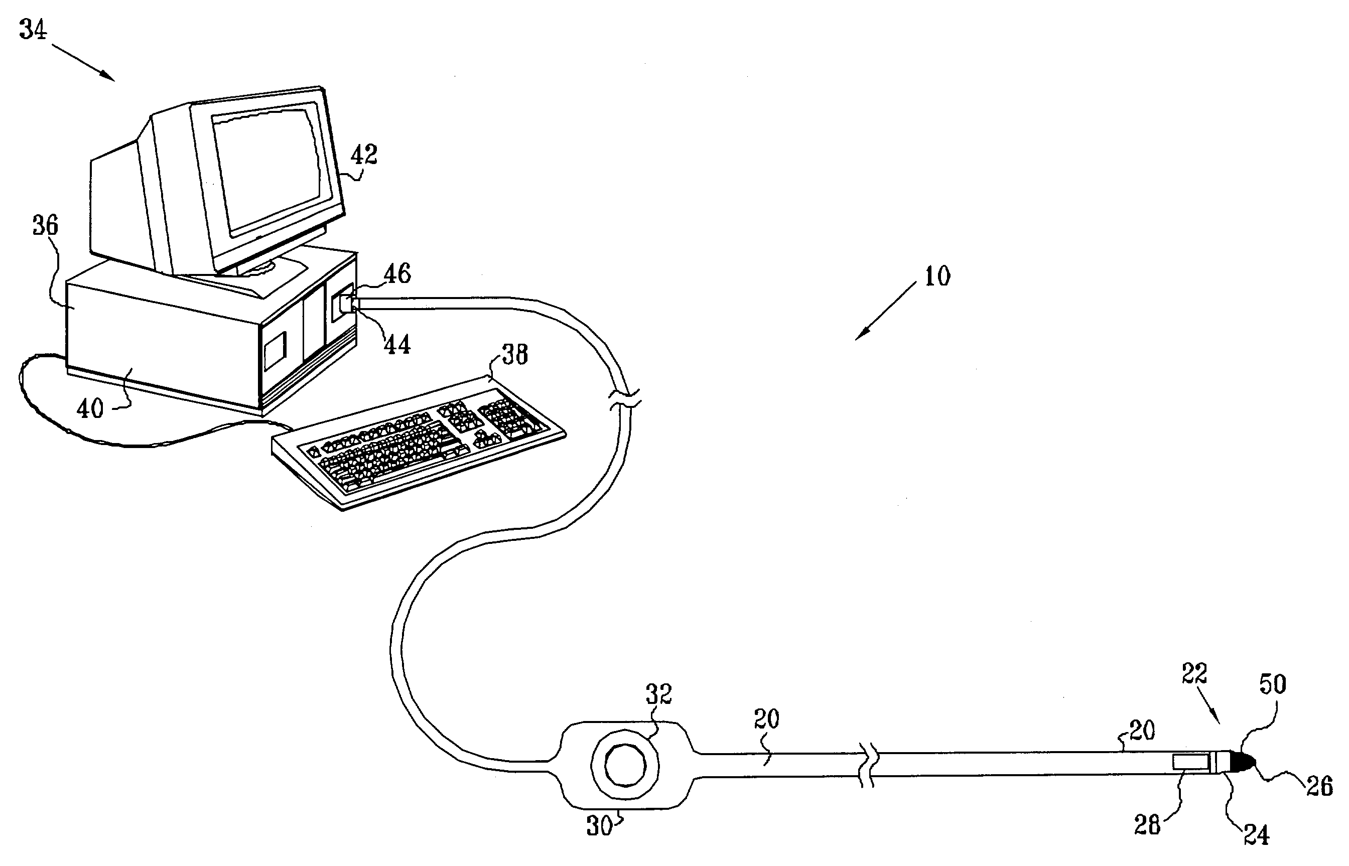
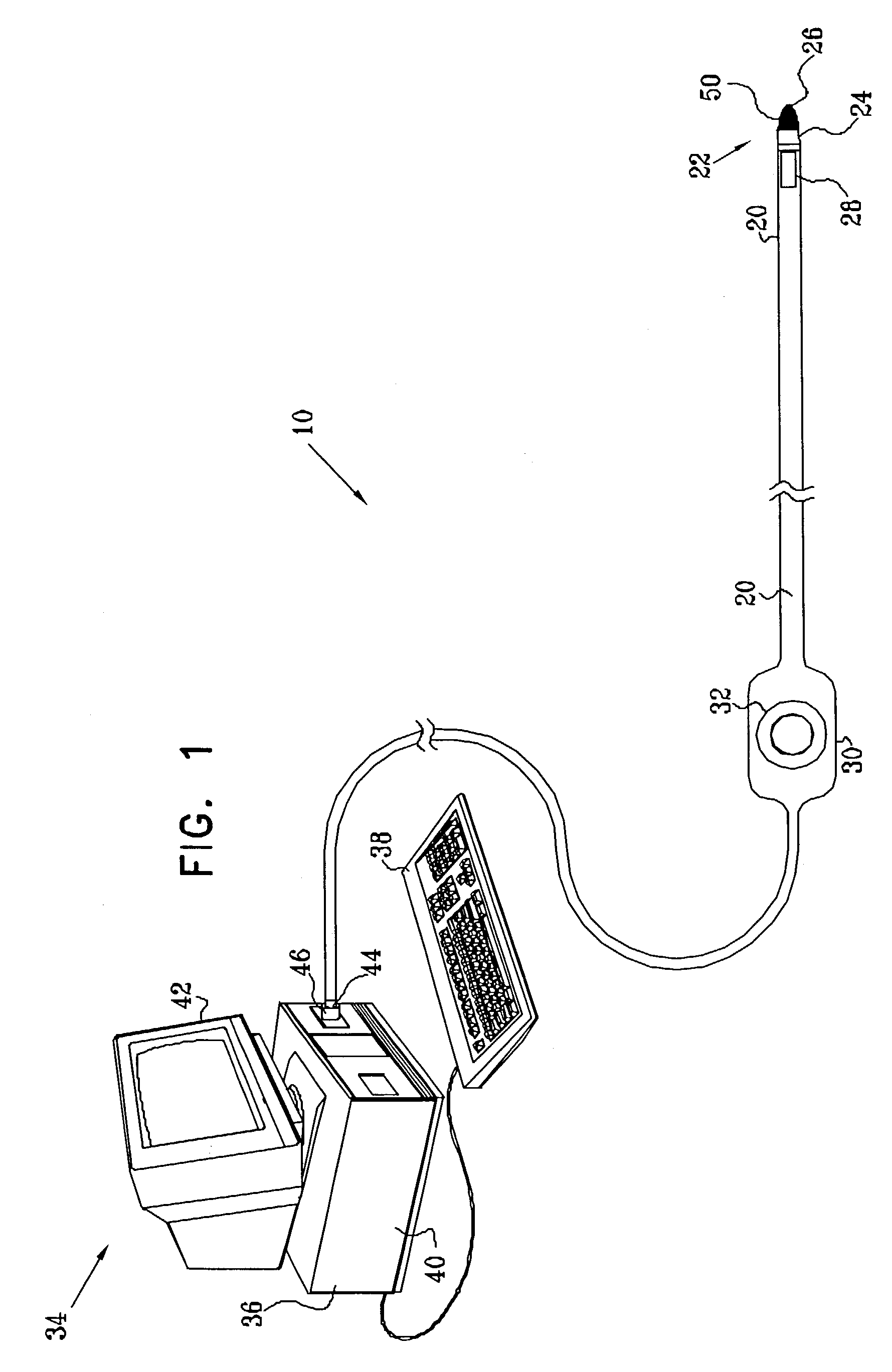
[0104]FIG. 1 is a simplified pictorial illustration of a catheter system 10 comprising an elongate probe, preferably a catheter 20, for insertion into the human body, in accordance with a preferred embodiment of the present invention. It is to be understood that although the following preferred embodiments are described with reference to a catheter, the present invention is equally applicable to other types of probes.

[0105]Catheter 20 preferably includes a handle 30 for operation of the catheter by a user, and controls 32 on handle 30 enable the user to steer a distal end 22 of the catheter in a desired direction, or to position and / or orient it as desired.

[0106]System 10 further comprises a console 34, which enables the user to observe and regulate the functions of catheter 20. Console 34 preferably includes a computer 36, a keyboard 38, signal processing circuits 40, which are typically inside the computer, and a display 42. Signal processing circuits 40 typically receive, amplify...


PUM


Abstract

Apparatus is provided for calibrating a probe having a position sensor and an ultrasonic transducer. The apparatus includes a test fixture, which includes an ultrasonic target disposed therein at a known position. A computer is adapted to receive a position signal generated by the position sensor while the transducer is in alignment with the ultrasonic target, determine an orientation of the probe in a frame of reference of the test fixture, and determine calibration data for the probe responsive to the orientation of the probe.

Description

FIELD OF THE INVENTION[0001]The present invention relates generally to systems for medical diagnosis and treatment, and specifically to medical catheters whose location can be detected.BACKGROUND OF THE INVENTION[0002]Various methods and devices have been described for determining the position of a probe or catheter tip inside the body using electromagnetic fields, such as in U.S. Pat. No. 5,391,199 to Ben-Haim, European Patent 0 776 176 to Ben-Haim et al., U.S. Pat. Nos. 5,833,608 and 6,161,032 to Acker, and U.S. Pat. Nos. 5,558,091 and 5,752,513 to Acker et al., all of which are assigned to the assignee of the present patent application and are incorporated herein by reference. U.S. Pat. No. 5,913,820 to Bladen et al. and U.S. Pat. No. 5,042,486 to Pfeiler et al., both of which are incorporated herein by reference, also describe electromagnetic position-determination systems. Other electromagnetic tracking systems, not necessarily for medical applications, are described in U.S. Pa...

Claims


Application Information

Patent Timeline
IPC IPC(8): A61B8/00A61B5/06A61B19/00A61B8/12
CPCA61B5/06A61B8/12A61B8/4254A61B8/58A61B19/5244H01F2005/027A61B2017/00725A61B2019/5251A61B2019/5276A61B2019/528A61B34/20A61B2090/3784A61B2034/2051A61B2090/378A61B5/062
Inventor GOVARI, ASSAF
Owner BIOSENSE
Learn More