
Method and apparatus for adaptive transmission control in a high data rate communication system

a communication system and high data rate technology, applied in the field of adaptive transmission control of high data rate packet data transmission in a wireless communication system, can solve the problems of stringent and fixed delay requirements, and achieve the effect of reducing unnecessary retransmission of packet data, improving the throughput of a high data rate cdma system, and high ra

Inactive Publication Date: 2006-08-08
QUALCOMM INC
View PDF20 Cites 76 Cited by
  • Summary
  • Abstract
  • Description
  • Claims
  • Application Information

AI Technical Summary

Benefits of technology

[0012]The present invention is directed to a novel and improved method and apparatus for high rate packet data transmission in a CDMA system. An exemplary system for transmitting high rate digital data in a wireless communication system is disclosed in copending U.S. patent application Ser. No. 08 / 963,386, entitled “METHOD AND APPARATUS FOR HIGHER RATE PACKET DATA TRANSMISSION,” (hereafter the '386 application) assigned to the assignee of the present application and incorporated by reference herein. The present invention advantageously improves the throughput of a high data rate CDMA system by minimizing unnecessary retransmissions of packet data within transmit time slots after successful decoding of the associated packet data by a destination network node such as a wireless subscriber station.
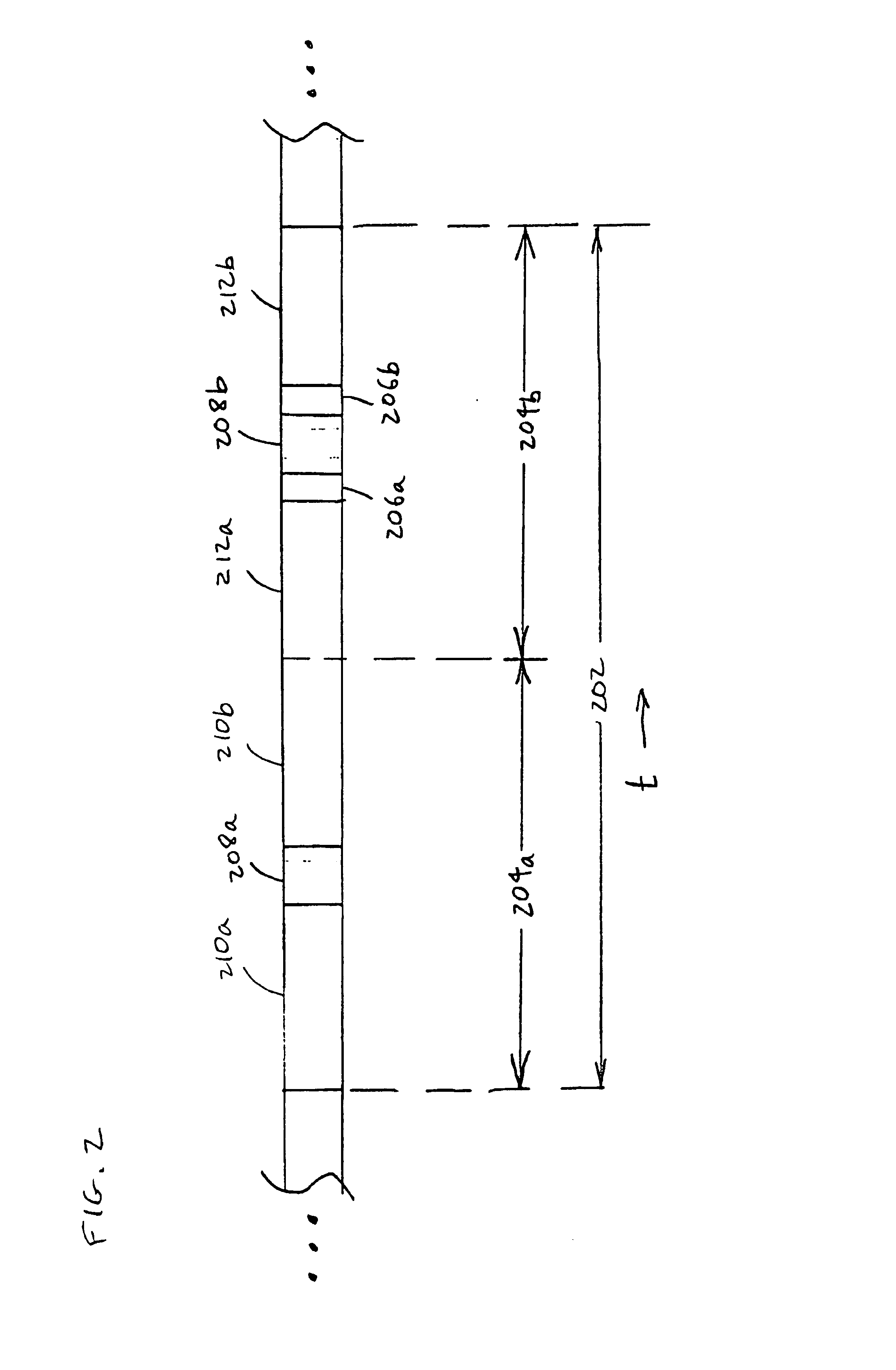
[0018]In an exemplary aspect, the base station may not increase the data rate of a multiple-slot packet once the first time slot of the packet has been transmitted. To avoid losing a multiple-slot packet when the forward link channel degrades, the data rates chosen for multiple-slot packets are very conservative. Often, if the forward link channel improves during the transmission of a multiple-slot packet, the destination subscriber station may successfully decode the packet before all of the multiple copies of the packet have been sent by the base station. The longer the period during which multiple-slot packets are transmitted, the greater is the probability that the C / I of the forward link will change and no longer match the subscriber station's requested DRC data rate. If the subscriber station successfully decodes the packet within less than the predetermined number of copies of the packet, transmitting the remaining copies of the packet is a waste of precious forward link bandwidth. In addition, if the forward link signal happens to fade during the transmission of a multiple-slot packet, then the data thus far accumulated for the packet might be prematurely discarded. Transmitting the packet for just one or two more slots might enable successful decoding and avoid wasting the signals transmitted in the previous time slots.

Problems solved by technology

A significant difference between voice services and data services is the fact that the former imposes stringent and fixed delay requirements.

Method used


Image

  • Method and apparatus for adaptive transmission control in a high data rate communication system
  • Method and apparatus for adaptive transmission control in a high data rate communication system
  • Method and apparatus for adaptive transmission control in a high data rate communication system

Examples


Embodiment Construction

[0030]FIG. 1 shows a first wireless base station 106a transmitting to subscriber stations within a coverage area 108a and a second wireless base station 106b transmitting to subscriber stations within a coverage area 108b that overlaps with coverage area 108a. Subscriber station 102a is located within coverage area 108a but not coverage area 108b. Subscriber station 102b is located within both coverage area 108a and coverage area 108b. Base station 108a transmits data to subscriber station 102a through communication channel 104a and to subscriber station 102b through communication channel 104b. Base station 108b transmits data to subscriber station 102b through communication channel 104c.

[0031]In an exemplary embodiment, each subscriber station 102 generates a signal quality metric based on signals received from base stations 106. A subscriber station 102b receiving forward link signals from multiple base stations 106 identifies the base station associated with the received signal ...


PUM


Abstract

In a high data rate communication system, a method and apparatus for improved throughput while transmitting data packets within multiple time slots. In order to avoid unnecessary retransmissions of a packet, a subscriber station sends a Stop-Repeat signal to a base station, causing the base station to cease further transmissions of the packet. In order to enable successful decoding of a packet, a subscriber station sends a Continue-Repeat signal to a base station, causing the base station to send retransmissions of the packet during time slots beyond a predetermined default number of time slots.

Description

BACKGROUND OF THE INVENTION[0001]I. Field of the Invention[0002]The current invention relates to wireless data communication. More particularly, the present invention relates to a novel and improved method and apparatus for high rate packet data transmission in a wireless communication system.[0003]II. Description of the Related Art[0004]A modern day communication system is required to support a variety of applications. One such communication system is a code division multiple access (CDMA) system which conforms to the “TIA / EIA-95 Mobile Station-Base Station Compatibility Standard for Dual-Mode Wideband Spread Spectrum Cellular System” and its progeny, hereinafter referred to as IS-95. The CDMA system allows for voice and data communications between users over a terrestrial link. The use of CDMA techniques in a multiple access communication system is disclosed in U.S. Pat. No. 4,901,307, entitled “SPREAD SPECTRUM MULTIPLE ACCESS COMMUNICATION SYSTEM USING SATELLITE OR TERRESTRIAL RE...

Claims


Application Information

Patent Timeline
IPC IPC(8): H04B7/212H04B7/00H04L1/00H04L1/08H04L1/16H04L1/18H04L29/08
CPCH04L1/0001H04L1/002H04L1/0025H04L1/0028H04L1/189H04L1/1809H04L1/1812H04L1/1838H04L1/1671H04L1/16
Inventor ATTAR, RASHIDPADOVANI, ROBERTOBLACK, PETER J.SINDHUSHAYANA, NAGABHUSHANA T.ESTEVES, EDUARDO A. S.GURELLI, MEHMET
Owner QUALCOMM INC
Learn More