Balancing skateboard

a technology of skateboards and balancing boards, applied in skateboards, vehicle components, sport apparatus, etc., can solve problems such as statically unstable, and achieve the effects of low friction resistance, good dynamic stability, and insensitivity to surface roughness

Inactive Publication Date: 2006-08-01
POTTER STEVEN DICKINSON
View PDF15 Cites 104 Cited by
  • Summary
  • Abstract
  • Description
  • Claims
  • Application Information

AI Technical Summary

Benefits of technology

[0016]The object of this invention is to provide a skateboard which can be self-propelled without pushing off on the ground while also providing low frictional resistance, insensitivity to surface roughness, good dynamic stability, the ability to significantly tilt the board in a turn, and the challenge of balancing the board.
[0017]Of the prior art, the present invention most closely resembles the Snakeboard, the primary difference being the use of a single wheel, ice-blade or ski-runner attached to each foot-pad. This allows the foot pads to tilt much further in a turn without requiring small wheel diameter or excessive height of the board off the ground. With the wheels or runners in line with the steering axis, surface irregularities do not affect the steering. Larger diameter wheels provide lower rolling resistance and less vibration on rough roads. For full off-road capability, the foot-pads can be mounted inside large diameter pneumatic wheels using large-bore thin-style bearings.
[0022]A partial list of additional enhancements to the invention is as follows: adjustable stops to prevent excessive rotation of the foot-pads, foot-straps to allow jumps and tricks, a dedicated boot / binding system, boots permanently attached, a wear-plate on the underside of the strut to allow “grinding” tricks, springs to align the wheels when the foot-pads are unloaded, a torsional spring in the strut to hold the two foot-pads coplanar while mounting the board, a wheel-cavity in the underside of the foot-pads to maximize the wheel diameter while minimizing overall height, suspension of the wheels to dampen vibration and road shocks, and a cable-activated hand brake.

Problems solved by technology

Lastly, the invention provides an exciting challenge in that it is not statically stable.

Method used


Image

  • Balancing skateboard
  • Balancing skateboard
  • Balancing skateboard

Examples


Embodiment Construction

[0038]The following description presents three preferred embodiments of the invention labeled I, II, III and IV for use on smooth pavement, rough surfaces, ice and snow, respectively. Additional variations and possible enhancements are also described.

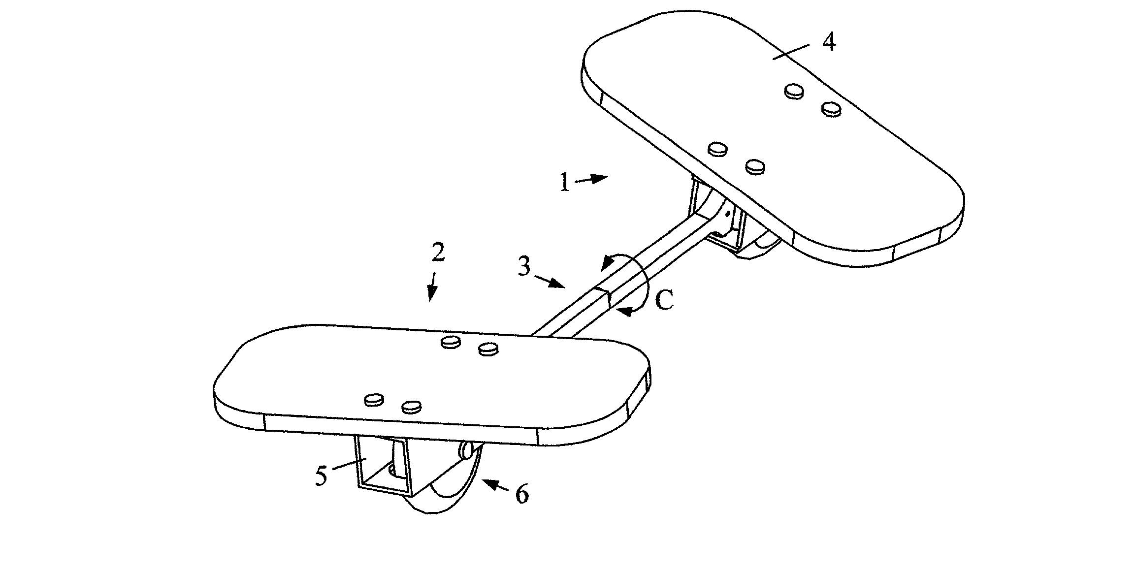
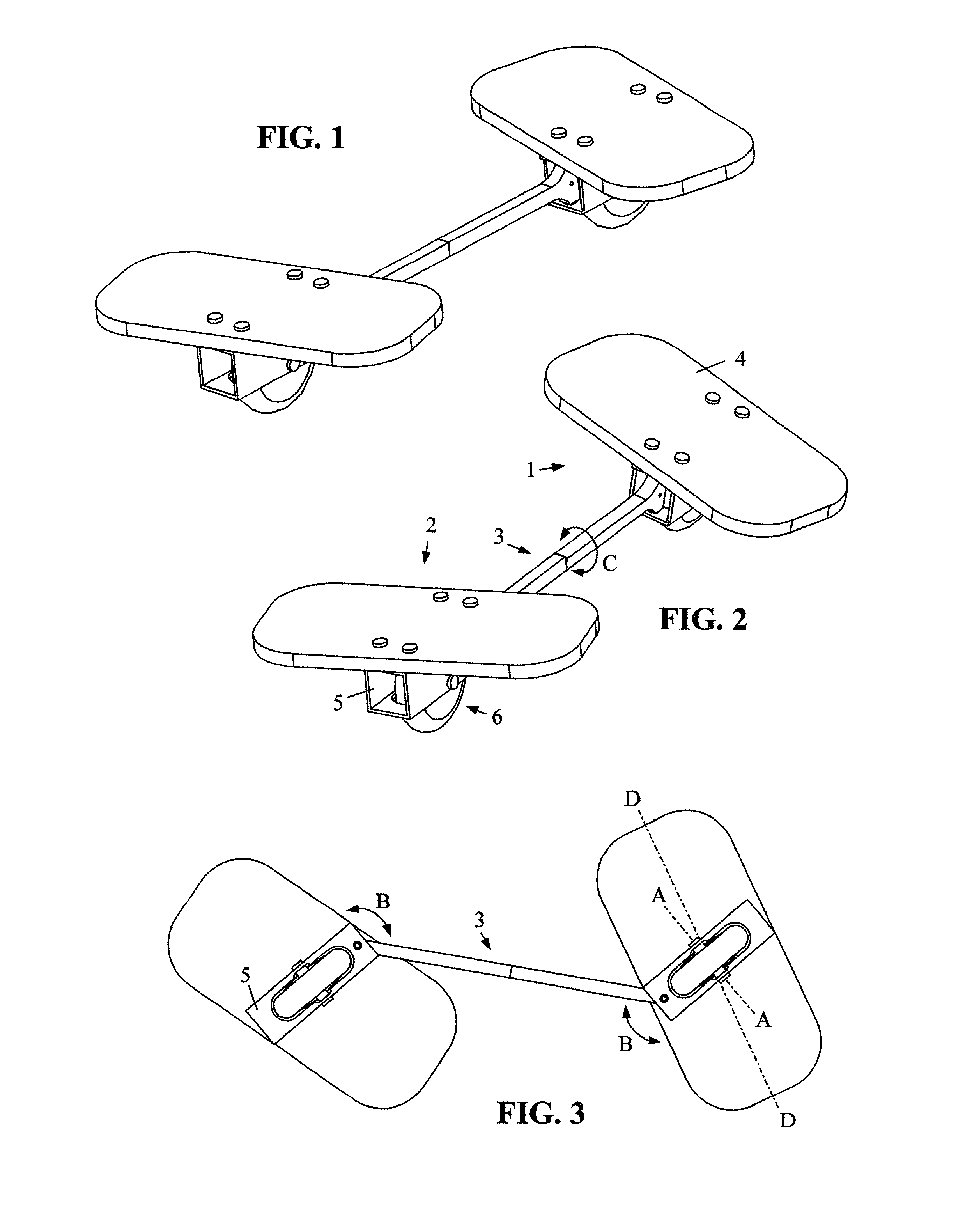
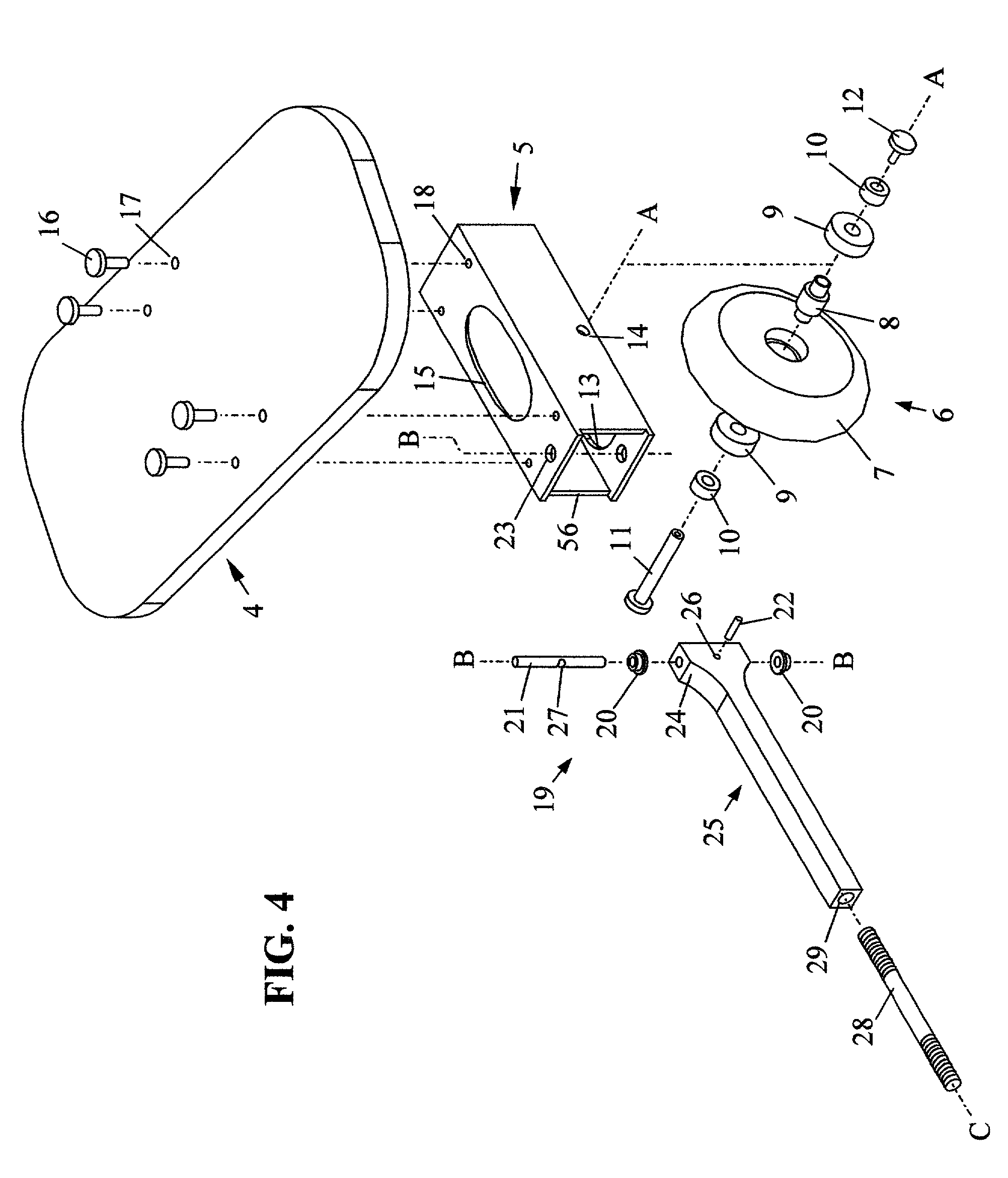
[0039]Embodiment I shown in FIGS. 1–7 includes a front footboard 1, a rear footboard 2 and strut 3 which connects the two footboards. The rider stands with one foot centered over each footboard and steers by pivoting one or both feet about the two vertical steering axes B. The strut in this case serves three functions: it restrains moments about the heel-toe axes D which would otherwise cause the ankle to turn, it supplies the inward force which would otherwise require excessive exertion of the rider's inner thigh muscles, and it reduces the risk of knee injury by limiting the steering travel. To minimize unwanted steering torque it is also desirable for the two footboards to tilt independently. This is achieved by allowing torsional ro...


PUM


Abstract

A skateboard for use on pavement, ice or snow using a single narrow-footprint wheel, ice-blade or ski-runner attached to each foot, thus requiring the rider to dynamically balance the board. The skateboard is capable of self-propulsion at considerable speed on the flat or uphill by using an undulating motion. It can also lean up to 30 degrees and has a steering circle of only two feet. The board's construction comprises a front footboard, a rear footboard, and a strut which connects the two footboards and resists bending and extension. Each footboard includes a footpad, an attachment (i.e. a wheel, blade or ski), and a pivot joint connecting to the strut. The axis of this joint is aligned perpendicular to the footpad which allows the rider to steer each footboard independently by torsionally rotating the lower leg.

Description

CROSS REFERENCE TO RELATED APPLICATIONS[0001]Not Applicable.STATEMENT REGARDING FEDERALLY SPONSORED RESEARCH OR DEVELOPMENT[0002]Not Applicable.REFERENCE TO A MICROFICHE APPENDIX[0003]Not Applicable.BACKGROUND OF THE INVENTION[0004]This invention relates to skateboards, or more generally, to devices for human locomotion involving rolling or sliding, on which the rider stands with one foot ahead of the other and controls the direction of travel by articulation of the feet.[0005]The classic skateboard design consists of a substantially rigid board elongated in the direction of travel having two wheel-sets mounted fore and aft to the underside of the board. These two wheel-sets, which each have two coaxial wheels spaced approximately 8 inches apart, are attached to the board using skateboard “trucks” which steer the wheels in response to left / right tilting of the board. The trucks also provide a spring-effect to resist tilting.[0006]This method of steering has three deficiencies: limit...

Claims


Application Information

Patent Timeline
IPC IPC(8): A63C17/01A63C17/06A63C17/18A63C17/22
CPCA63C17/004A63C17/013A63C17/18A63C17/223A63C17/016A63C2203/40
Inventor POTTER, STEVEN DICKINSON
Owner POTTER STEVEN DICKINSON
Why Eureka
Try Eureka