
System and method for communicating with a remote communication unit via the public switched telephone network (PSTN)

a communication unit and public switched technology, applied in the field of communication systems, can solve the problems of inability to communicate with a remote communication unit via the public switched telephone network, inability to easily provide a phone jack, and inability to meet the needs of remote communication units,

Inactive Publication Date: 2006-07-18
STATSIGNAL IPC
View PDF553 Cites 159 Cited by
  • Summary
  • Abstract
  • Description
  • Claims
  • Application Information

AI Technical Summary

Problems solved by technology

However, in many situations phone jacks are not readily available.
However, existing configurations have several drawbacks.
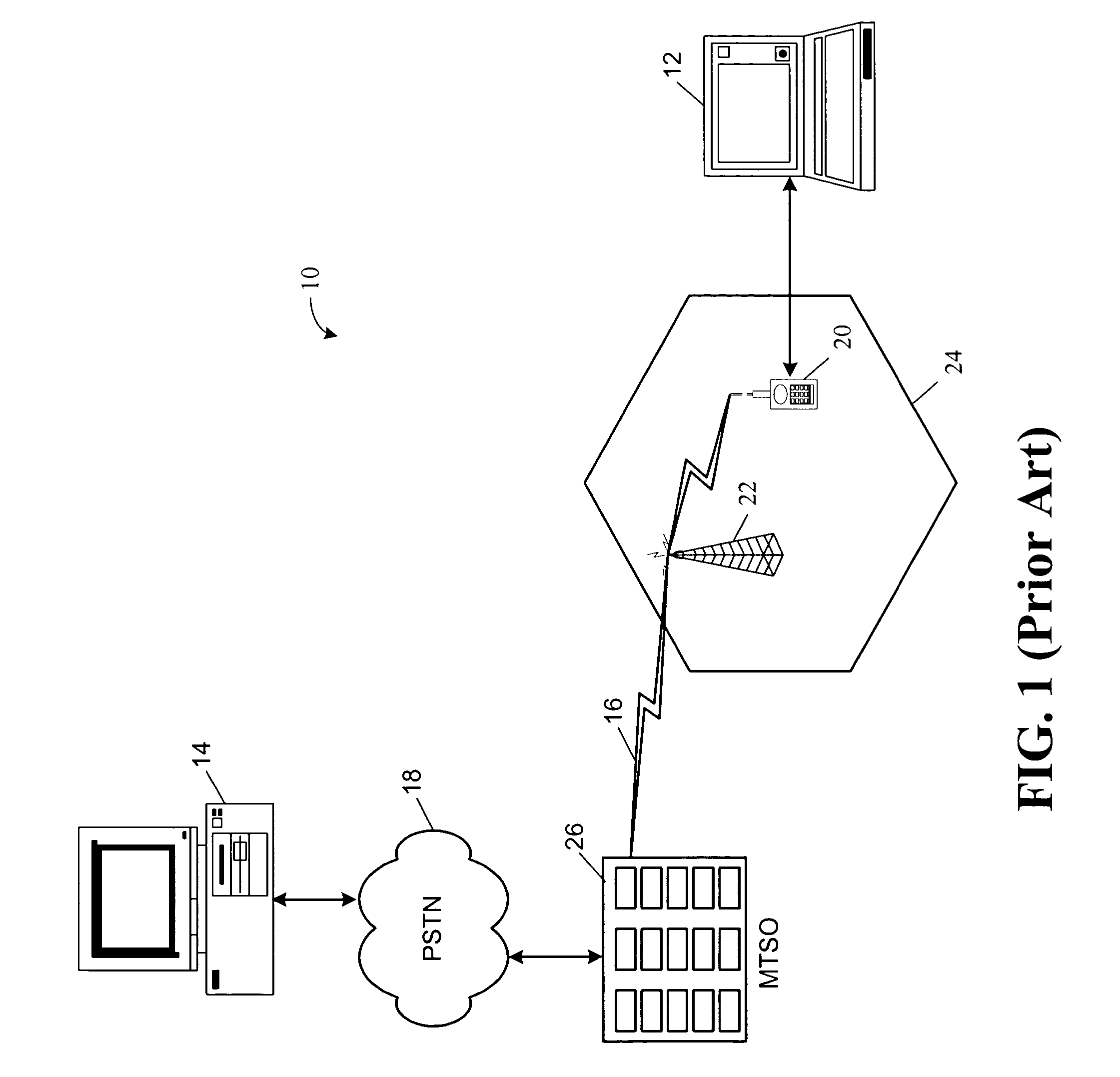
First, the communication channel established in a cellular link is inherently noisy and, therefore, unreliable.
As a result, many errors can occur, leading to retransmissions of data, which slow down the effective communication link.
In addition, most cellular service providers charge a relatively substantial fee for cellular phone usage.

Method used


Image

  • System and method for communicating with a remote communication unit via the public switched telephone network (PSTN)
  • System and method for communicating with a remote communication unit via the public switched telephone network (PSTN)
  • System and method for communicating with a remote communication unit via the public switched telephone network (PSTN)

Examples


first embodiment

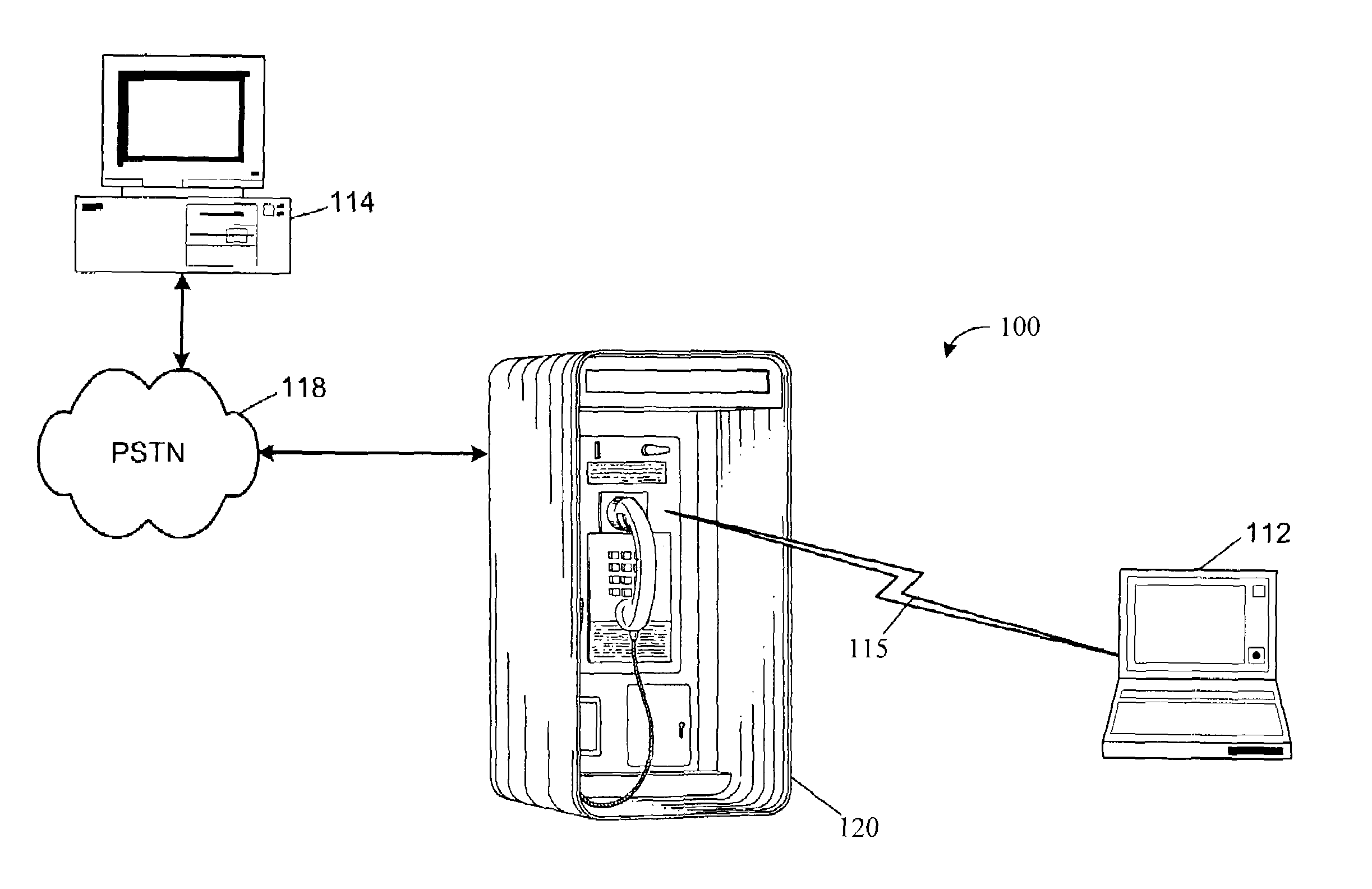
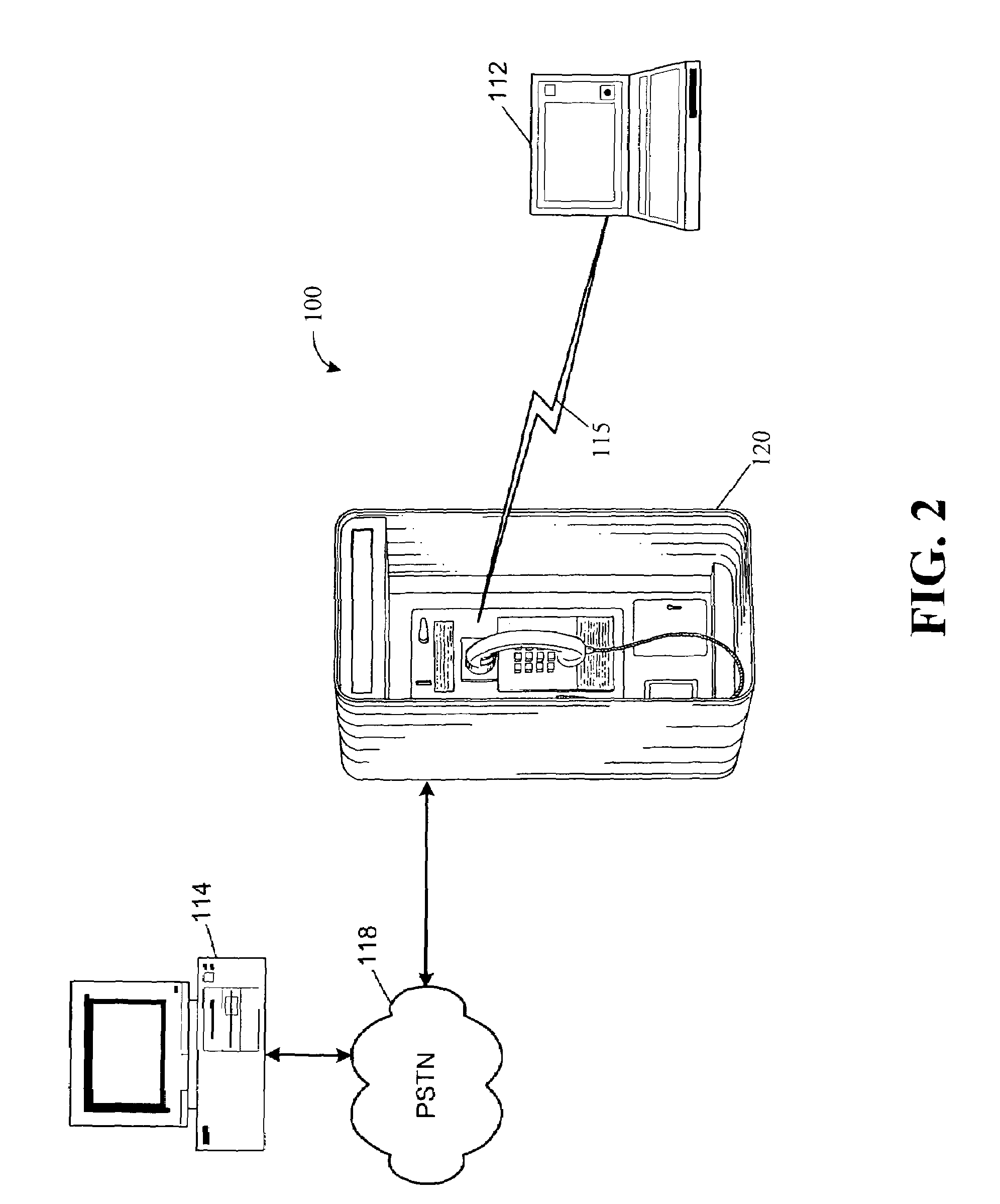
[0049]The portable telephone 705 of system 700 digitizes a user's analog voice signals into data packets. The digitization process is typically performed by a digital signal processor (DSP) embedded within the portable phone 705. The data packets are then delivered across RF link 115 from RF transceiver 160 (FIG. 4) to RF transceiver 122 in telephone 120. The data packets may be assembled using the well known internet protocol (IP) which provides error checking and addressing. Telephone 120 may also have an embedded DSP for decoding the data packets sent from the RF transceiver 160 back into analog voice signals. The voice signals are then circuit-switched as a normal telephone call to provide POTS band voice communication over the PSTN 118 to remote telephone 140. One will appreciate that according to this embodiment, because telephone 120 circuit switches the call between the telephone 120 and the remote telephone 140, telephone 120 is not be able to accommodate simultaneous commu...

second embodiment

[0054]One will appreciate that according to this second embodiment telephone 120 is able to accommodate simultaneous voice communication using handset 128 (FIG. 3) on the same connection to the PSTN as portable telephone 705. Thus, the functional operation described by system 300 (FIG. 6) would be implemented to control access to the telephone 120 by portable handset 705.

[0055]It will be appreciated that this embodiment enables physical placement of a remote communication unit 114 in a location that enables a user to make what is typically a long distance call with only charges related to the local access at telephone 120 and any other connection fees associated with accessing the remote communication unit 114. Thus, using software and computer techniques that are now well known, a voice call can be placed over the PSTN, utilizing the Internet, to a very distant remote telephone 140, whereby long distance telephone calling is effectively achieved without the associated long distance...


PUM


Abstract

The present invention is generally directed to a system and method for communicating between a personal data access device and a remote communication unit. In accordance with one aspect of the invention, a device, electrically connected for communication with a public switched telephone network (PSTN), is provided for facilitating communications between a personal data access device and a remote communication unit disposed in communication with the PSTN. The device includes a radio frequency (RF) transceiver configured for communication with a remote RF transceiver associated with the personal data access device, via an RF link, and a controller, responsive to communications received from the remote RF transceiver to maintain two-way communication between the personal data access device and the remote communication unit via the PSTN and the RF link.

Description

CROSS REFERENCE TO RELATED APPLICATIONS[0001]This application is a continuation-in-part of U.S. patent application Ser. No. 09 / 301,671, filed on Apr. 28, 1999, now U.S. Pat. No. 6,618,578, and entitled “System and Method for Communicating with a Remote Communication Unit Via the Public Switched Telephone Network (PSTN),” which is a continuation-in-part of U.S. patent application Ser. No. 08 / 895,720, filed on Jul. 17, 1997, and entitled “Transmitter for Accessing Pay-Type Telephones,” now U.S. Pat. No. 5,926,531, which, in turn, is a continuation-in-part of U.S. patent application Ser. No. 08 / 825,576, filed on Mar. 31, 1997, and entitled “Transmitter for Accessing Automated Financial Transaction Machines,” which claims the benefit of U.S. Provisional Patent Application Ser. No. 60 / 040,316, filed Feb. 14, 1997, and entitled “Card Replacement Transceiver For Use With Automatic Teller Machines,” each of which are hereby incorporated by reference.FIELD OF THE INVENTION[0002]The present i...

Claims


Application Information

Patent Timeline
Patent Type & Authority Patents(United States)
IPC IPC(8): H04B7/00G06Q20/00G07F7/00
CPCG06Q20/02G07F17/0014G06Q20/04
Inventor PETITE, THOMAS D.DAVIS, JAMES
Owner STATSIGNAL IPC
Learn More