
Method and apparatus for providing scalable pre-compressed digital video with reduced quantization based artifacts

a digital video and quantization technology, applied in the field of pre-compressed, stored video, can solve the problems of annoying artifacts, error propagating temporally over several frames, and omitted elements not relevant to understanding their operation

Inactive Publication Date: 2006-07-11
INTEL CORP
View PDF25 Cites 75 Cited by
  • Summary
  • Abstract
  • Description
  • Claims
  • Application Information

AI Technical Summary

Benefits of technology

[0016]The present invention avoids the aforementioned artifacts by providing a set of transition data that can be interframe decoded between decoding of a first bitstream (at a first bit rate) and a second bitstream (at a second bit rate). The transition data compensates for visual discrepancies between a decoded version of the first bitstream and a decoded version of the second bitstream. Thus, after a first bitstream has been decoded, the transition data is decoded, and then the second bitstream. The second bitstream provides a continuation of the video sequence that was begun with the first bitstream, and the transition data compensates for visual artifacts that would otherwise be present due to the difference in the bit rates of the first and second bitstreams.
[0018]The LBIFs inserted into the second bitstream provide points of correspondence between the image data of the two bitstreams in that the effects of the coarser quantization (or different spatial resolution) of the first bitstream are periodically introduced to the second bitstream. These LBIFs therefore provide points in the temporal progression of the video sequence at which a change from one bitstream to the other may be made, without the introduction of any significant visual artifacts into the decoded video. Thus, when switching from the first bitstream to the second bitstream, it is most desirable to have the first frame received from the second bitstream be a frame that follows an LBIF. Similarly, when switching from the second bitstream to the first bitstream, it is desirable to have the last frame received from the second bitstream be an LBIF. In this way, the two frames will be as closely related as possible.
[0019]This embodiment of the invention preferably makes use of LBIFs in a video-on-demand server. Multiple bitstreams are stored to be decoded using different relative bit rates. For all but the bitstream having the lowest bit rate, LBIFs are periodically inserted into the bitstreams from the bitstream having the next lower bit rate. Thus, the server has the same video sequence at different bit rates, with LBIFs to enable switching between the bitstreams. As the server is streaming the video data at one bit rate, a request for a different bit rate (higher or lower) is satisfied by switching to another stored bitstream at the temporal point in the video sequence corresponding to an LBIF in the bitstream having the higher bit rate. Effectively seamless bit rate “throttling” is therefore accomplished with a minimization of artifacts.
[0021]In another alternative embodiment, the input video signal is periodically coded in intraframe mode, such that frames of data are generated which correspond to interframe coded frames of the lowest rate bitstream, but which include all of the data necessary to independently recreate that frame of the video sequence. This embodiment does not have the high level of data compression of the preferred embodiment, but allows for random access. LBIFs are used in the higher rate bitstreams as points at which one may switch between the bitstreams with a minimum of quantization-based artifacts. However, the intraframe coded frames allow a user to begin the video sequence at any of the temporal points corresponding to the location of the intraframe coded frames. If a higher bit rate is thereafter desired, the rate may be increased at the appropriate LBIF locations, as described above. This embodiment is also useful in that it allows for fast forward and fast rewind of the video sequence by displaying the intraframe coded frames only, thus allowing a user to search quickly through the video sequence.

Problems solved by technology

If a transmission error causes a discrepancy to arise between the prediction signal at the transmitter and the prediction signal at the receiver, the error propagates temporally over several frames.
In practice, this error propagation may result in an annoying artifact which may be visible for several seconds in the decoded, reconstructed signal.
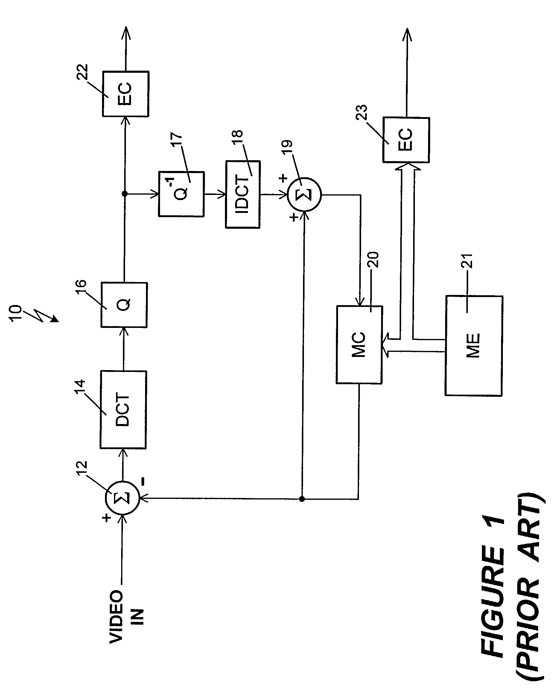
However, this type of hybrid coder is known in the art, and the omitted elements are not germane to understanding its operation.
Since the quantizer maps each coefficient to one of a finite number of quantization levels, there is an error introduced by the quantizer, the magnitude of which increases with a decreasing number of quantization levels.
The error introduced into the signal by quantizer 16 reduces the quality of the image which is later decoded, the reduced quality being a side effect of the data compression achieved through quantization.
In practice, if a compressed video signal such as the one output from the coder of FIG. 1 is transmitted over unreliable channels (e.g. the internet, local area networks without quality of service (QoS) guarantees, or mobile radio channels), it is particularly vulnerable to transmission errors.
Certain transmission errors have the characteristic of lowering the possible maximum throughput (i.e. lowering the channel capacity or “bandwidth”) of the transmission medium for a relatively long period of time.
Such situations might arise due to a high traffic volume on a store-and-forward network such as the internet, or due to an increasing distance between a transmitter and receiver of a mobile radio channel.
However, if the video has been coded and stored previously, the bit rate is chosen in advance, making such a request difficult to satisfy.
A problem arises, however, if it becomes necessary to change the bit rate during the transmission.
However, if the sequences are interframe coded, the switchover produces annoying artifacts due to the difference in the image quality of the two bitstreams.
However, the use of I-frames, requiring a significant amount of data, dramatically increases the overall bit rate.
The method does not support different frame rates for the video at different quality levels but, rather, for different spatial resolutions.
More importantly, in this method, the enhancement layer cannot be transmitted and decoded independently; it always requires the transmission and decompression of the base layer first.
This makes bandwidth-adaptive serving a complicated task, leads to inefficient compression, and ultimately affects the performance of the whole system.

Method used


Image

  • Method and apparatus for providing scalable pre-compressed digital video with reduced quantization based artifacts
  • Method and apparatus for providing scalable pre-compressed digital video with reduced quantization based artifacts
  • Method and apparatus for providing scalable pre-compressed digital video with reduced quantization based artifacts

Examples


Embodiment Construction

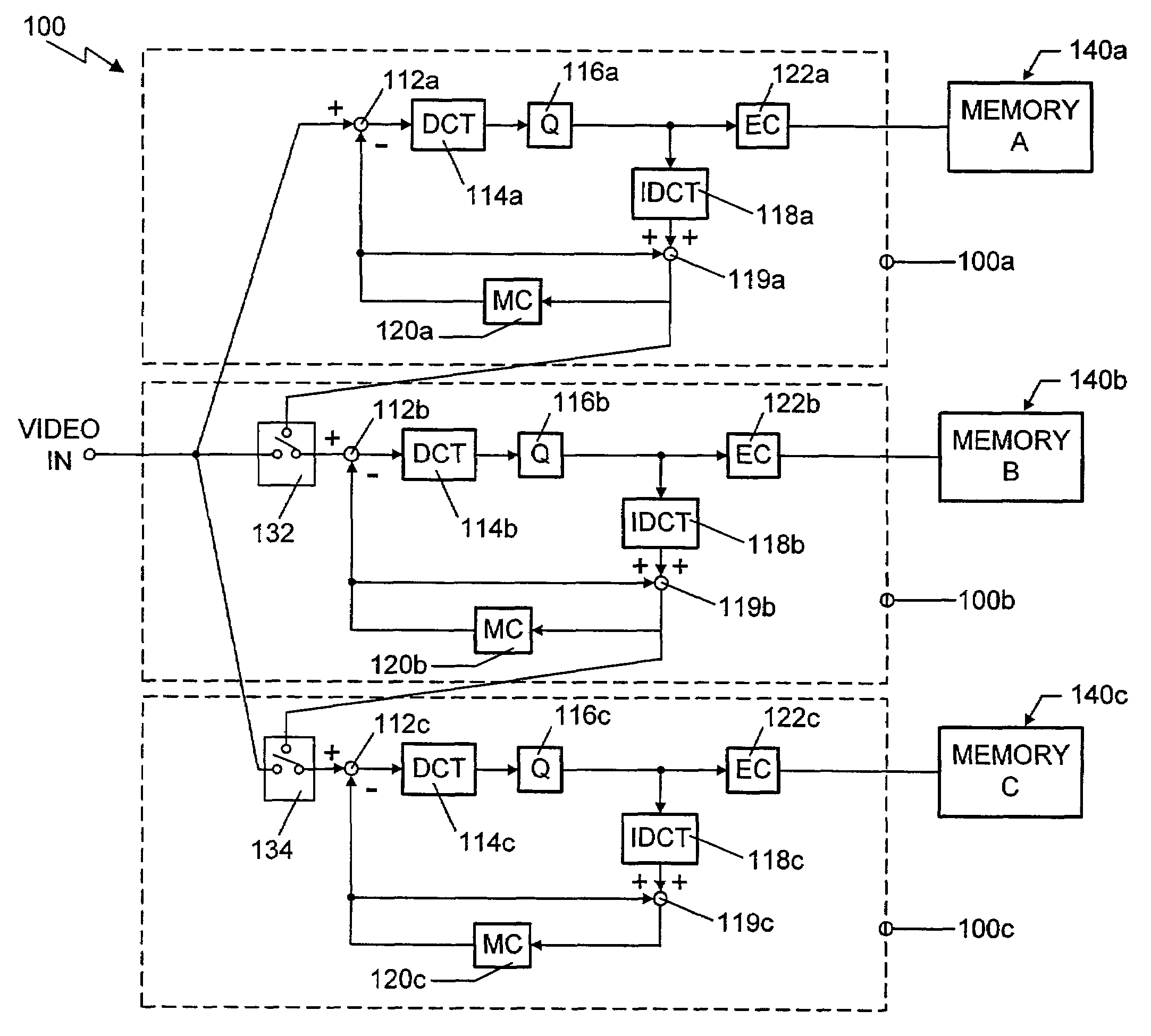
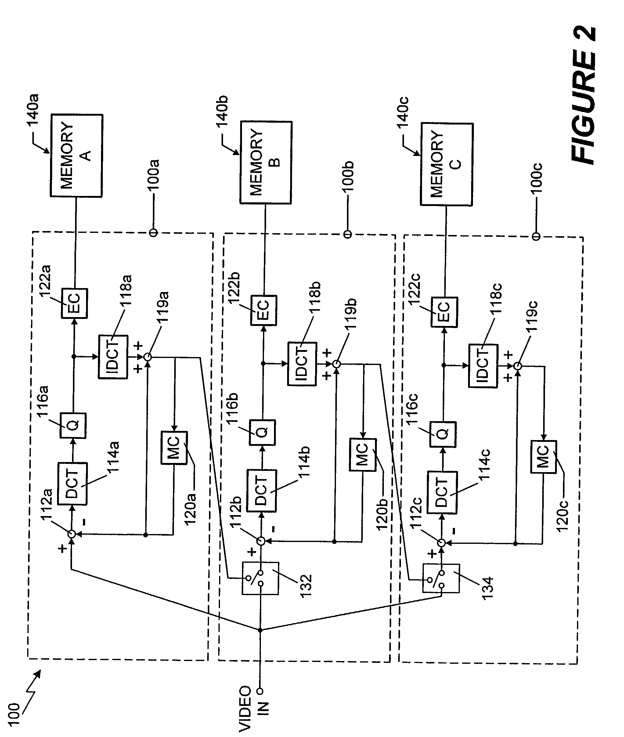
[0042]An interframe coding apparatus 100 according to the present invention is shown schematically in FIG. 2. The coding apparatus 100 contains three embedded coders 100a, 100b and 100c, each of which supplies data at a different bit rate. It will be recognized by those skilled in the art that the coding apparatus 100 may consist of any plural number of embedded coders, so as to allow the support of any desired number of different bit rates. It will also be understood that the coders 100a, 100b, 100c may be any type of interframe coder, and still make use of the inventive principles described herein. The preferred embodiment for each of the embedded coders 100a, 100b, 100c, however, are of essentially the same structure as the prior art coder of FIG. 1. Some of the more important details of the coders are discussed briefly above in conjunction with FIG. 1.

[0043]The coding apparatus 100 of FIG. 2 is arranged to allow the coding and storage of the same video signal at a variety of dif...


PUM


Abstract

A method for generating a digital motion video sequence at a plurality of bit rates uses a transitional coding source when switching between bitstreams having different bit rates during transmission of a video sequence. The transitional data may be frames coded using reconstructed frames reconstructed for a first bitstream using the characteristics of the second bitstream. These “low bit rate insert frames,” or LBIFs, contain the image characteristics of a signal coded at the lower bit rate. With a bitstream having a higher bit rate being periodically coded using an LBIF, a point of image continuity between the two bitstreams is provided. Thus, switching from one bitstream to the other at this point in the video sequence minimizes the production of artifacts caused by differences in bit rate. In another embodiment of the invention, a separate set of transitional data is created, taking the form of “switch” frames, or S-frames. The S-frames are typically the difference between a frame of a first bitstream and a frame of a second bitstream. These frames are inserted into the decoded bitstream during the transition from one bitstream to the other, and compensate for any visual artifacts that might otherwise occur due to the difference in bit rate of the two bitstreams.

Description

CROSS-REFERENCE TO RELATED APPLICATIONS[0001]This is a continuation of U.S. patent application Ser. No. 09 / 177,406, filed Oct. 23, 1998 now U.S. Pat. No. 6,480,541, which is a continuation-in-part of Ser. No. 08 / 753,618, filed Nov. 27, 1996 now abandoned.FIELD OF THE INVENTION[0002]This invention relates to the field of compressed motion video and, more specifically, to pre-compressed, stored video for video-on-demand applications.BACKGROUND OF THE INVENTION[0003]Digital video signals are typically compressed for transmission from a source to a destination. One common type of compression is “interframe” coding, such as is described in the International Telecommunications Union-Telecommunications (ITU-T) Recommendations H.261 and H.262, or the Recommendation H.263. Interframe coding exploits the spatial similarities of successive video frames by using previous coded and reconstructed video frames to predict the current video signal. By employing a differential pulse code modulation (...

Claims


Application Information

Patent Timeline
Patent Type & Authority Patents(United States)
IPC IPC(8): H04N7/12H04N7/26H04N7/36H04N7/46H04N7/50H04N7/66H04N9/804H04N21/234H04N21/2343H04N21/2662H04N21/6379H04N21/647
CPCH04N9/8042H04N19/59H04N21/23439H04N21/2662H04N19/105H04N19/172H04N19/51H04N19/61H04N19/12H04N19/152H04N19/187H04N19/39H04N21/23424H04N21/6379H04N21/64769
Inventor GIROD, BERNDERICSSON, STAFFANRESZNIK, YURIY A.FARBER, NIKOLAUS
Owner INTEL CORP
Learn More