
Combustible gas detector having flow-through sensor container and method for measuring such gases

a gas detector and sensor technology, applied in the field of combustion gas detectors having flow-through sensor containers and methods for measuring such gases, can solve the problems of reducing sensor sensitivity, prolonging sensor response time, and provoking false sensor readings

Inactive Publication Date: 2006-06-20
BAKER HUGHES INC
View PDF14 Cites 7 Cited by
  • Summary
  • Abstract
  • Description
  • Claims
  • Application Information

AI Technical Summary

Benefits of technology

The invention is a method and detector for measuring combustible gases using a catalytic sensor. The method involves drawing a gas sample into a chamber, interrupting the flow of gas, and measuring the output of the sensor synchronously with the interruption of the gas flow. The detector includes a flow-through chamber with a port for connecting to the ambient gas mixture and a catalytic sensor of combustible gases installed inside the chamber. The detector can measure the concentration of combustible gases in the gas sample by analyzing the dynamics of the sample burning and comparing the output signal with a reference signal. The detector can also measure the sensor sensitivity by applying a difference between the output signals during the gas sample application. The technical effects of the invention include improved accuracy and efficiency in measuring combustible gases in ambient gas mixtures.

Problems solved by technology

Gas velocity variations around the sensor in this case may provoke false sensor readings.
Prior attempts to reduce measurement error due to gas velocity variations tend to diminish the sensor sensitivity and prolong the response time of the sensor.
Combustion heating on the sensing bead causes the resistance of the RTD imbedded into sensing bead change with respect to the resistance of the reference bead RTD to create a bridge misbalance.
However, the bridge misbalance in a conventional detector may be influenced by factors other than the catalytic combustion on the sensing bead, including: aging of the beads, changes in the background such as variations in ambient temperature, non-combustible gas mixture composition, and radiation absorption in the vicinity of the sensor beads due to different moisture concentrations.
These other factors may significantly raise the lower detection limit of the detector, and cause the response of the detector to drift out of its rated detection level or range for combustible gases.
Reduced sensitivity to combustible gases and sensor drift are troublesome for a catalytic detector, especially for those used in critical applications, such as lower explosive limit (LEL) detectors that are employed to prevent fire and explosions.
With diffusion type sensors, this procedure is relatively cumbersome.
Moreover, long periods of time, e.g. up to several months, may pass between when the detector looses sensitivity and when the sensitivity loss in the detector is discovered.
A poisoned detector may fail to detect a dangerous level of combustibles.
Implementation of automated or frequent manual sensitivity check-up in a conventional detector is usually cost-prohibitive.
This temperature selection technique may not be effective at discriminating between different compositions with two or more combustible gases while using a single sensor and at one fixed temperature.
In particular, catalytic bead sensors are practically unable to discriminate between carbon monoxide (CO) and hydrogen (H2) gases.
Accordingly, conventional catalytic detectors tend to be ineffective at: measuring low combustible gases concentrations, e.g., concentrations below 500 ppm (parts per million) over an extended time period, maintaining a stable “zero” without drifting over a period of years, and distinguishing between combustible gases, e.g. between CO and H2.

Method used


Image

  • Combustible gas detector having flow-through sensor container and method for measuring such gases
  • Combustible gas detector having flow-through sensor container and method for measuring such gases
  • Combustible gas detector having flow-through sensor container and method for measuring such gases

Examples


Embodiment Construction

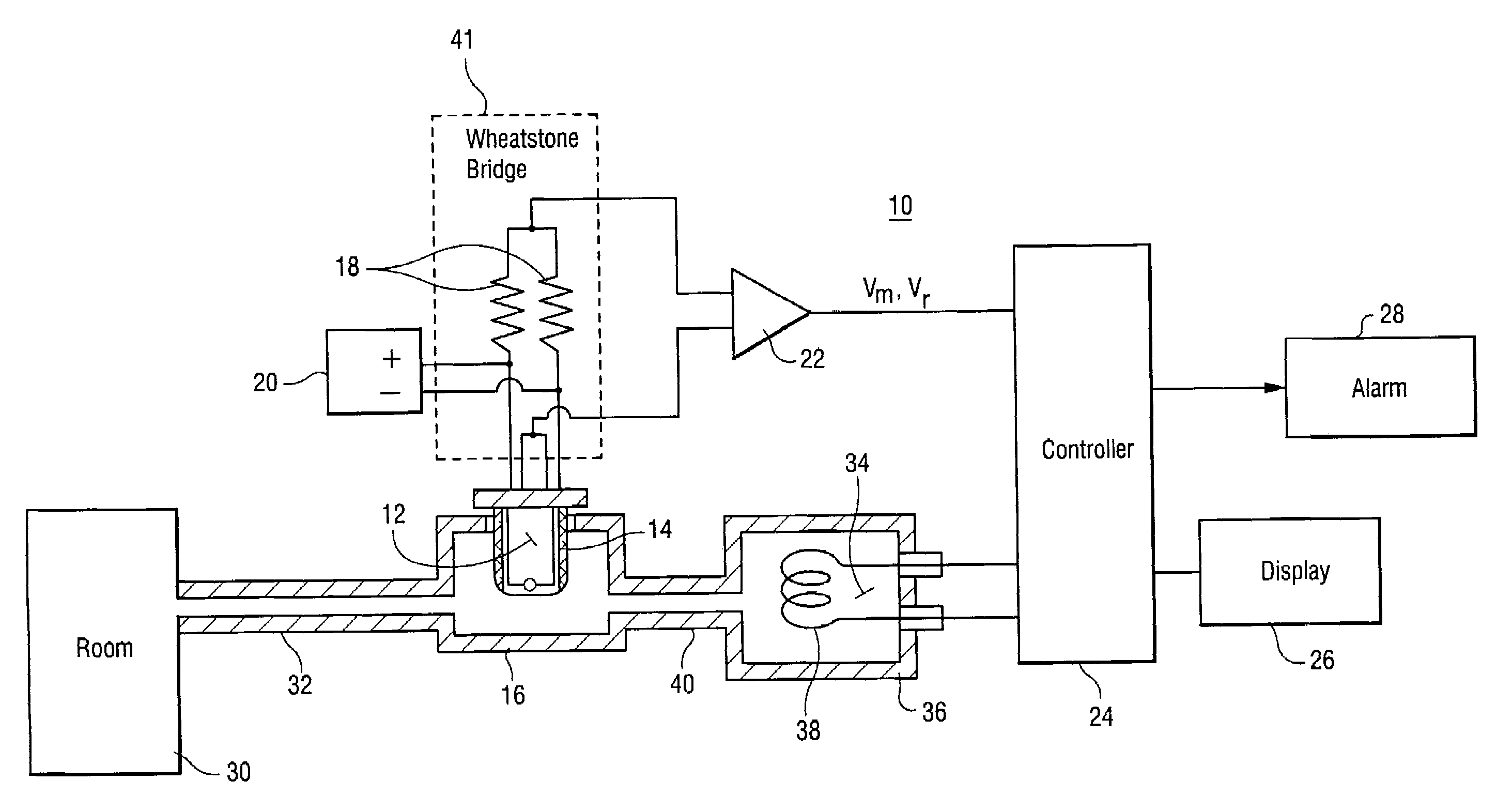
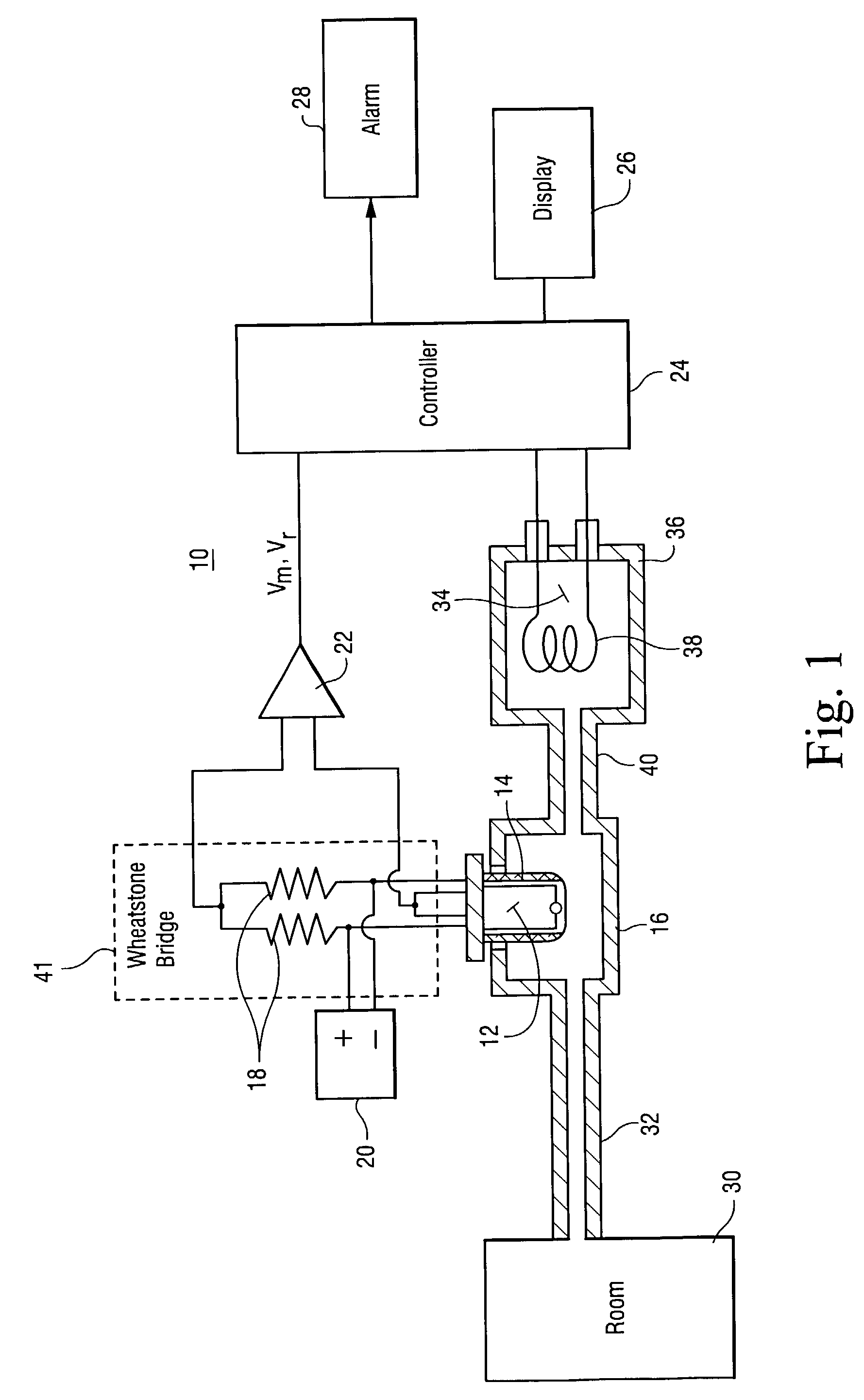
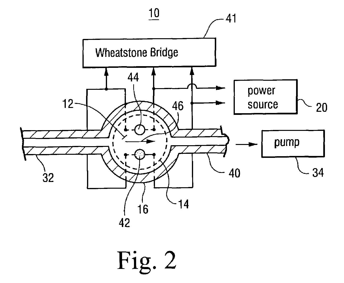
[0019]FIG. 1 shows a combustible gas detector 10 having a combustible gas sensor 12 in a porous or other protective enclosure 14 and housed in a flow-through chamber 16. In this design, the protective enclosure 14 is optional and is shown because it is commonly installed by sensor manufacturers in commercially available catalytic sensors. The chamber 16 is impervious to ambient gas diffusion and may be separated from an ambient gas volume 30 by a substantial distance, e.g. up to 10 meters. The chamber has a sample gas inlet pneumatically connected to volume 30 by a diffusion limiting passage 32, and an exhaust passage 40. The passage 32 essentially prevents the diffusion of ambient gas from the volume 30 into the chamber 16 while allowing to drawing in a gas sample by convection. The sensor 12 in the chamber 16 may be a catalytic combustible sensor such as, for example, a conventional catalytic bead sensor having a catalytic sensing bead and a reference bead that are connected as th...


PUM

PropertyMeasurementUnit
interior diameteraaaaaaaaaa
lengthaaaaaaaaaa

Abstract

An apparatus and method to measure combustible gases using a catalytic sensor includes: housing the catalytic sensor in a flow-through chamber isolated from a volume of ambient gas; periodically drawing into the chamber a sample of the ambient gas; burning on the catalytic sensor and in the chamber the combustible gas in the sample of ambient gas, e.g. essentially until the completion of burn out, and measuring the plurality of output signals of the sensor synchronously with the interrupted ambient gas sampling while burning the sample on the catalytic sensor.

Description

BACKGROUND OF THE INVENTION[0001]There are several known methods to detect the presence and measure the concentration of combustible gases and vapors (collectively referred to herein as “combustible gases” or “combustibles”). In one such method, the combustible gases are detected based on the actually measuring the rate of heat liberation during catalytic combustion. A combustible gas detector detects and measures combustible gases by burning a gas sample on a catalytic sensor. Catalytic combustion occurs in the sensor on a surface of a heated porous substrate, e.g. silica or alumina that has been impregnated with a catalyst. The resulting increase in temperature of the substrate is proportional to the rate of heat generation during the catalytic combustion and is measured electronically by sensing a resistance change of an imbedded resistance temperature detector (RTD).[0002]A known type of catalytic combustible gas detector has a catalytic bead sensor, a reference bead, and a Whea...

Claims


Application Information

Patent Timeline
Patent Type & Authority Patents(United States)
IPC IPC(8): G01N7/00G01N1/24G01N27/16
CPCG01N27/16G01N1/24
Inventor GOKHFELD, YUZEF
Owner BAKER HUGHES INC
Learn More