Transmitter circuits

a technology of transceivers and circuits, applied in waveguide devices, modulation, amplifier modifications to reduce non-linear distortion, etc., can solve the problems of non-constant envelope modulation, inherently less efficient, and the use of linear power amplifiers for amplification of non-constant envelope rf signals, so as to increase efficiency and save costs.

Active Publication Date: 2006-06-13
WSOU INVESTMENTS LLC
View PDF8 Cites 56 Cited by
  • Summary
  • Abstract
  • Description
  • Claims
  • Application Information

AI Technical Summary

Benefits of technology

[0010]By removing the need for a power supply modulator, the switching noise and limited efficiency associated with such modulators is removed. In addition, cost savings can be achieved, while creating EER transmitters with improved efficiency for linear modulation schemes.
[0013]By combining tough and non-critical direct gain compensation with envelope feedback, high linearisation of the amplifier envelope transfer function can be achieved. This aspect of the invention can also be combined with any suitable solution for the phase path such as an offset loop or a direct fractional synthesis.
[0023]By detecting and acting on the loss of feedback control, the use of a circulator, or isolator, between the amplifier and impedance load is rendered unnecessary, so increasing efficiency and saving on cost.

Problems solved by technology

However, recent types of communication system such as EDGE and UMTS use non-constant envelope modulation schemes.
The drawback is that the amplification of non-constant envelope RF signals requires the use of linear power amplifiers, which are inherently less efficient.
The lower power efficiency of linear amplifiers translates into higher power consumption and higher heat dissipation.
However, many of these devices and techniques are unsuitable for battery operated portable devices such as mobile telephones, or are incapable of meeting current RF design standards, such as the TETRA linearity standard, ETSI publication ETS 300 396-2; “Trans-European Trunked Radio (TETRA);-Voice plus Data (V+D)—Part 2: Air Interface (AI)”; March 1996.
Such circuits suffer from the inherent problem that the phase and envelope information propagates through separate paths, which introduces different delays on the phase and envelope components before they are combined again at the output of the transmitter.
This leads to distortion of the modulation.

Method used


Image

  • Transmitter circuits
  • Transmitter circuits
  • Transmitter circuits

Examples


Embodiment Construction

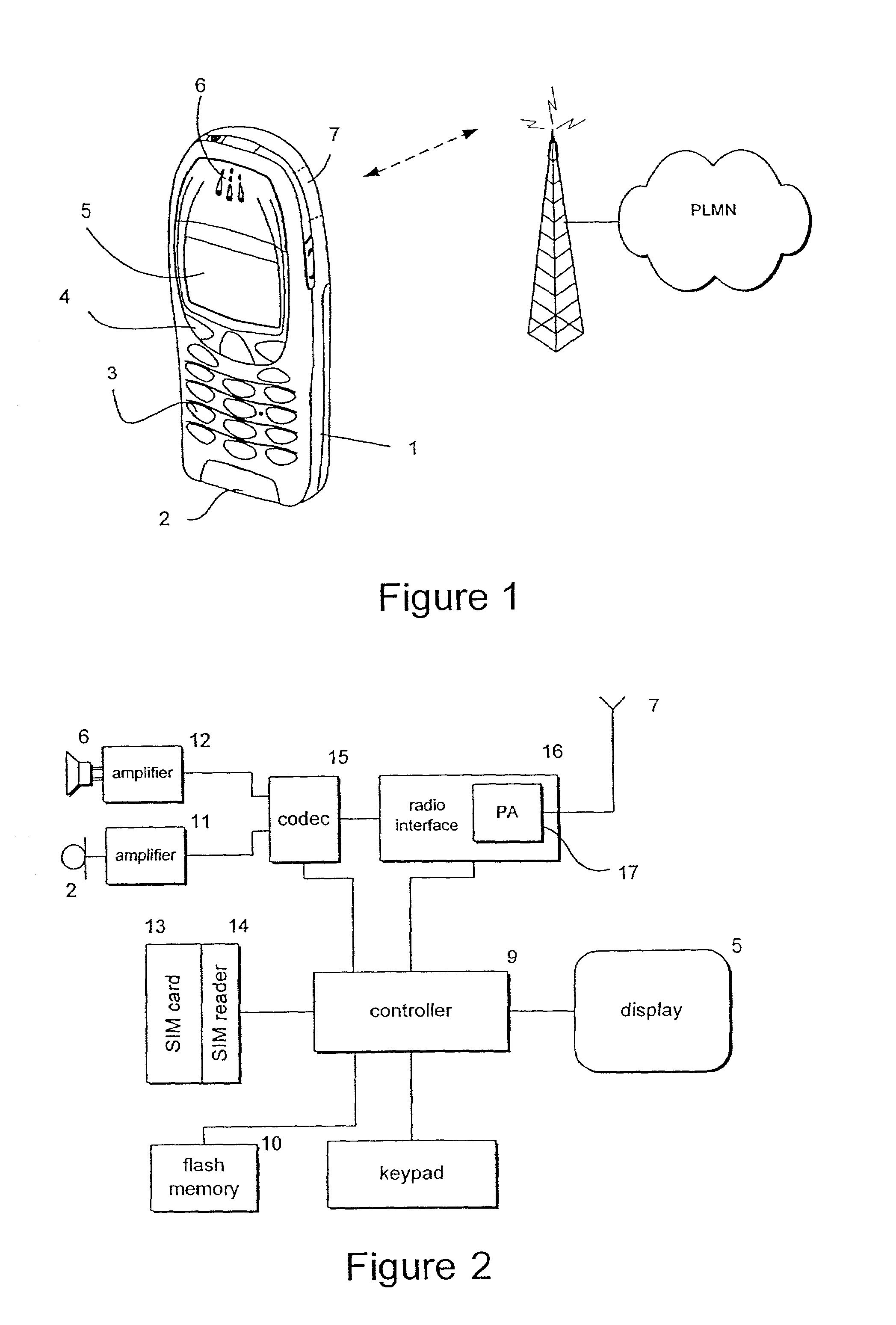
[0040]Referring to FIG. 1, a mobile station in the form of a mobile telephone handset 1 includes a microphone 2, keypad 3, with soft keys 4 which can be programmed to perform different functions, an LCD display 5, a speaker 6 and an antenna 7 which is contained within the housing.

[0041]The mobile station 1 is operable to communicate through cellular radio links with individual public land mobile networks (PLMNs) operating according to communication schemes such as UMTS and EDGE.

[0042]FIG. 2 illustrates the major circuit components of the telephone handset 1. Signal processing is carried out under the control of a digital micro-controller 9 which has an associated flash memory 10. Electrical analogue audio signals are produced by microphone 2 and amplified by pre-amplifier 11. Similarly, analogue audio signals are fed to the speaker 6 through an amplifier 12. The micro-controller 9 receives instruction signals from the keypad and soft keys 3, 4 and controls operation of the LCD displ...


PUM


Abstract

A polar loop transmitter includes separate phase and envelope paths providing a linearising scheme for an efficient non-linear power amplifier. Loop filters are included in each of the phase and envelope paths to enable the path characteristics to be matched to one another. A polar loop transmitter and other types of envelope elimination and restoration transmitters control the output envelope of the power amplifier by connecting the output of the envelope detector, or in an envelope feedback transmitter, the envelope error signal, to the bias control input of the power amplifier. The transmitter can further include compensation means for compensating for non-linearities in the envelope control means and a loss of feedback control detector to ensure that the feedback signal remains within acceptable limits.

Description

FIELD OF THE INVENTION[0001]The present invention relates to transmitter circuits, particularly but not exclusively to power amplifier linearising circuits such as envelope elimination and restoration transmitters and polar loop transmitters for use in portable communications devices such as mobile telephones.BACKGROUND[0002]The present trend in portable communications devices such as mobile telephones is to increasingly lightweight devices with increased talk-time between battery recharge cycles. Such developments require ever more efficient radio-frequency (RF) amplifiers to minimise power consumption. In cellular systems such as GSM, the modulation scheme is a constant amplitude scheme, also referred to as constant envelope modulation, which permits use of efficient non-linear amplifiers. However, recent types of communication system such as EDGE and UMTS use non-constant envelope modulation schemes. The drawback is that the amplification of non-constant envelope RF signals requi...

Claims


Application Information

Patent Timeline
IPC IPC(8): H01Q11/12H03F1/32
CPCH03F1/3247H03F1/3282H03F1/0227H03F2201/3233H03F2200/102
Inventor MIDTGAARD, JACOBBAGGER, OLUF
Owner WSOU INVESTMENTS LLC
Why Eureka
Try Eureka