
Inter-network relay system and method

a relay system and relay technology, applied in the field of relay systems and methods in the internet field, can solve the problems of not enabling end-to-end bandwidth guarantees in the network infrastructure, not considering relay priority for individual packets, and not enabling vpn b>16000/b> service providers to make guaranteed minimum bandwidth services available using the intern

Inactive Publication Date: 2006-06-13
KK TOSHIBA
View PDF8 Cites 96 Cited by
  • Summary
  • Abstract
  • Description
  • Claims
  • Application Information

AI Technical Summary

Benefits of technology

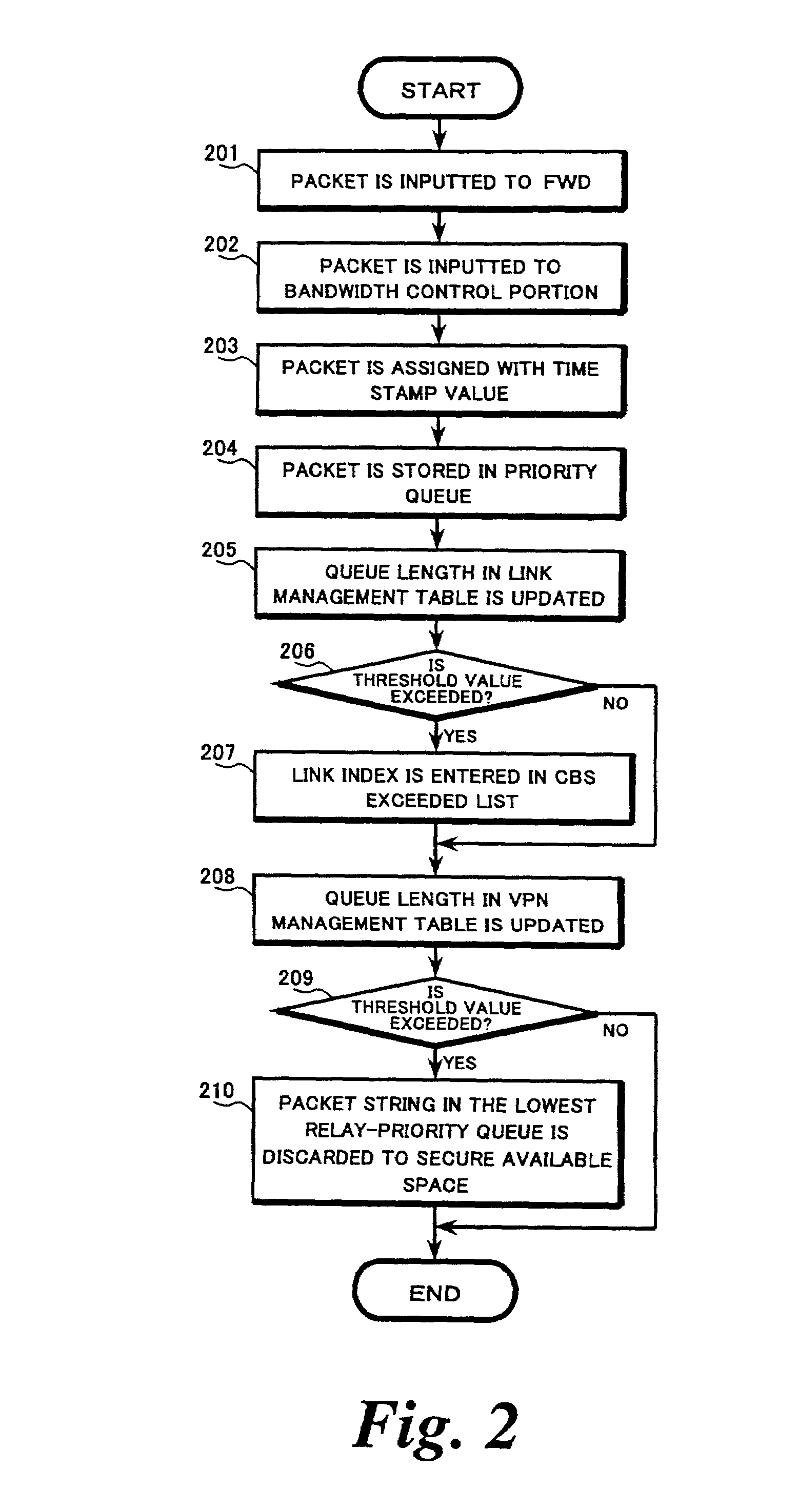
[0026]In accordance with another embodiment of the present invention, a transfer scheduling method in an inter-network relay unit is provided, comprising setting a first threshold value of queue length for each queue; setting a second threshold value of queue length for a total length of all queues; storing packets in a plurality of queues acc

Problems solved by technology

However, such a network infrastructure does not enable end-to-end bandwidth guarantees.
However, VPN 16000 service providers have not made guaranteed minimum bandwidth service available using the Internet.
However, conventional minimum bandwidth guarantee methods, such as frame relay, do not consider the relay priority for individual packets when selecting packets to be marked for preferential discard.
Therefore, the user's guaranteed minimum bandwidth is not optimally allocated.
However, even when the quantity of tokens in the bucket is insufficient, the packet may be transferred after attaching a mark indicating traffic in excess of the guaranteed minimum bandwidth.
The supply of packets to be transferred may be limited; therefore the supply of tokens to the bucket may be stopped when the quantity of tokens reaches this limited value because the traffic rate may be less than the minimum guaranteed bandwidth for a long period of time, such as an hour.
However, in such a system, smaller token units require faster computational logic for deducting tokens from the counter of each bucket.
Such a system would be complicated and large in size.

Method used


Image

  • Inter-network relay system and method
  • Inter-network relay system and method
  • Inter-network relay system and method

Examples


Embodiment Construction

[0045]Reference will now be made in detail to the exemplary embodiments of the invention, examples of which are illustrated in the accompanying drawings. Hereinafter, the term “packet” is used for convenience in the explanation. However, the invention is not restricted in applicability to packet data itself, but may also be applicable to attribute information related to each packet, such as, for example, a message including pointer information indicating an address of a storage buffer area and a packet length.

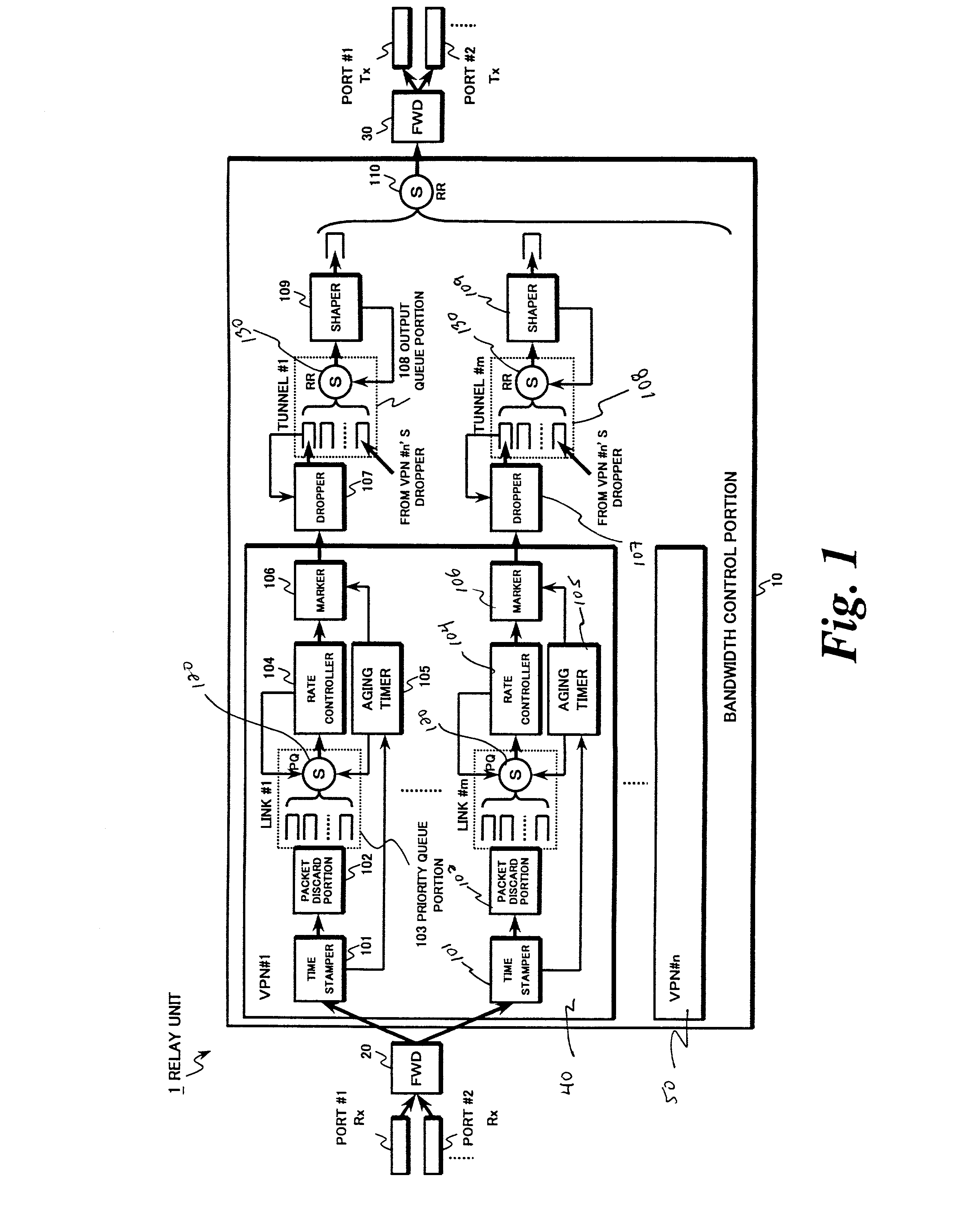
[0046]FIG. 1 is a block diagram of an exemplary configuration for a relay unit 1 such as a virtual private network (VPN) router, in accordance with methods and systems consistent with the present invention. The relay unit 1 includes a bandwidth control portion 10 for scheduling packet transfer based on each relay priority, a first packet forwarder (FWD) 20 for identifying a flow based on information stored in a header portion of each packet received from each port, for assignin...


PUM


Abstract

An inter-network relay unit is provided that is capable of simultaneously achieving guaranteed minimum bandwidth and priority control (including relay priority, discard priority, delay priority, etc.). A rate controller outputs relatively high priority packets from priority queues as guaranteed traffic based on guaranteed bandwidth for each link. Relatively low priority packets left in the priority queues are marked for preferential discard and output as best-effort traffic by an aging timer. When an output port is congested, an output queue portion discards only the marked packets. Thus, traffic having a plurality of relay priorities can use the guaranteed minimum bandwidth effectively and the guaranteed minimum bandwidth can be secured, irrespective of change in traffic volume for each relay priority level.

Description

CROSS-REFERENCE TO RELATED APPLICATIONS[0001]This application claims the benefit of priority from Japanese Patent Application No. 2000-375809, filed on Dec. 11, 2000; the entire contents of which are incorporated herein by reference.FIELD OF THE INVENTION[0002]The present invention relates to devices that transfer communication packets, such as transmission control protocol / internet protocol (TCP / IP) packets. The present invention further relates to devices that provide guaranteed bandwidth, priority control and scheduling of packet transfers.BACKGROUND[0003]With an increase in popularity of Internet communications, the Internet infrastructure has expanded significantly. Inter-network relay units, such as bridges and routers, have been used to couple different segments of the Internet infrastructure. Bridges perform packet transfer processes for each destination using a data link layer and routers do the same using a network layer. A network infrastructure configured from convention...

Claims


Application Information

Patent Timeline
IPC IPC(8): H04L12/28H04L12/56H04L47/6275
CPCH04L47/10H04L47/32H04L47/31H04L47/22
Inventor HORIGUCHI, AKIHIROMURONO, TAKAHIRO
Owner KK TOSHIBA
Learn More