
Apparatus and method for measuring unsteady pressures within a large diameter pipe

a technology of unsteady pressure and apparatus, which is applied in the direction of liquid/fluent solid measurement, digital computer details, instruments, etc., can solve the problems of affecting the process, prone to clogging, and other methods such as ultrasonics, are susceptible to air or stratified flow, and meters that use rotating wheels or moving parts are subject to reliability problems

Active Publication Date: 2006-06-06
EXPRO METERS
View PDF85 Cites 69 Cited by
  • Summary
  • Abstract
  • Description
  • Claims
  • Application Information

AI Technical Summary

Problems solved by technology

For example, invasive techniques that rely on insertion of a probe into the flow, or geometry changes in the pipe, may be disruptive to the process and prone to clogging.
Other methods such as ultrasonics may be susceptible to air or stratified flow.
Meters that use rotating wheels or moving parts are subject to reliability issues.
Coriolis meters are limited when pipe diameters become large due to the increase in force required to vibrate the pipe.
However, if the steam entering or exiting the turbine were saturated, pressure and temperature measurement would not sufficient to determine the specific enthalpy, but rather, a measure of the quality of the steam would be required to uniquely define the thermodynamic properties of the saturated steam mixture.
If the fluid at either or both locations is saturated, pressure and temperature measurements alone will not be enough to determine the enthalpy.

Method used


Image

  • Apparatus and method for measuring unsteady pressures within a large diameter pipe
  • Apparatus and method for measuring unsteady pressures within a large diameter pipe
  • Apparatus and method for measuring unsteady pressures within a large diameter pipe

Examples


Embodiment Construction

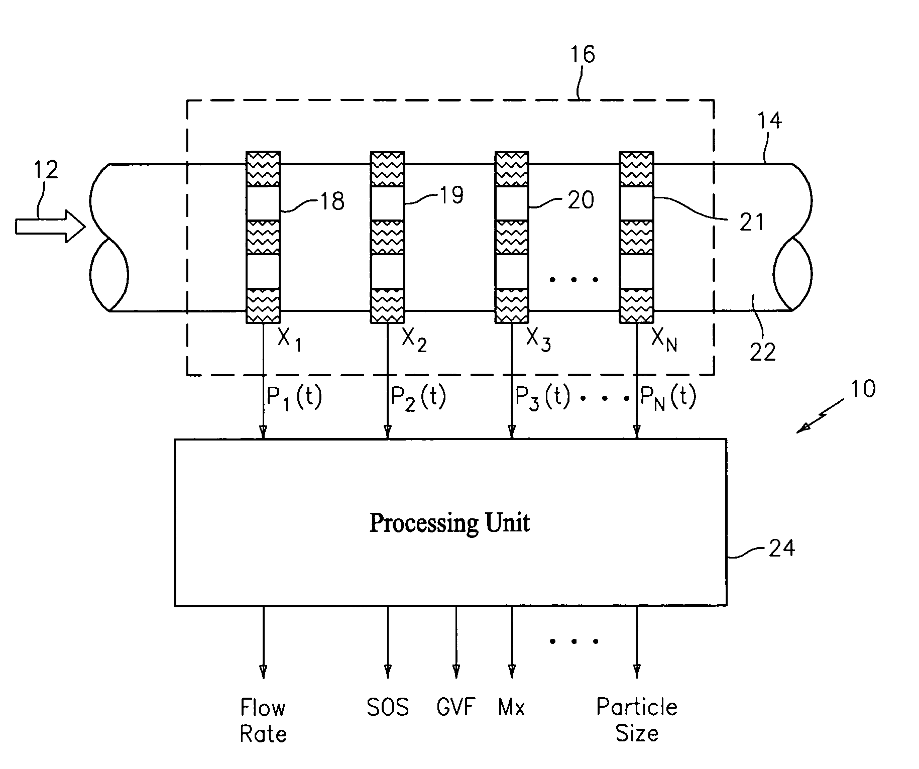
[0043]Referring to FIG. 1, an apparatus or flow meter, generally shown as 10, is provided to measure the unsteady pressures (P(t)) of a homogeneous or non-homogeneous fluid 12 flowing within a pipe or conduit 14 to determine a parameter or characteristic of the fluid. The apparatus described herein after is particularly advantageous for measuring certain characteristics of fluid flowing through large diameter pipes, which is greater than six inches in diameter. The apparatus is scalable to any large diameter pipe greater than six inches. In fact, one embodiment of the present invention has been demonstrated on a pipe having an outer diameter of at least 55 inches.

[0044]The flow meter 10 can measure the velocity and / or volumetric flow rate of a single phase fluid 12 (e.g., gas, liquid or liquid / liquid mixture) and / or a multi-phase mixture 12 (e.g., process flow) flowing through a pipe. The multi-phase mixture may be a two-phase liquid / gas mixture, a solid / gas mixture or a solid / liqui...


PUM

PropertyMeasurementUnit
diameteraaaaaaaaaa
outer diameteraaaaaaaaaa
thicknessaaaaaaaaaa

Abstract

An apparatus 10 is provided that includes a spatial array of at least two unsteady pressure sensors 18–21 placed at predetermined axial locations x1–xN disposed axially along a pipe 14 for measuring at least one parameter of a fluid 12 flowing in the pipe 14. The pressure sensors 18–21 comprise a plurality of pressure sensing elements such as piezoelectric film sensors 23 for measuring unsteady pressures associated with acoustical pressures and / or vortical disturbances. The sensing elements are disposed circumferentially around the pipe and spaced a predetermined distance. The pressure signals P1(t)–PN(t) provided by the pressure sensors 18–21 are processed by a processing unit to provide an output signal indicative of a parameter of the fluid.

Description

CROSS-REFERENCE TO RELATED APPLICATIONS[0001]This application claims the benefit of U.S. Provisional Patent Application No. 60 / 482,515 filed Jun. 24, 2003, U.S. Provisional Patent Application No. 60 / 441,652 filed Jan. 22, 2003, U.S. Provisional Patent Application No. 60 / 441,395 filed Jan. 21, 2003, U.S. Provisional Patent Application No. 60 / 441,373 filed Jan. 21, 2003, which are all incorporated herein by reference.TECHNICAL FIELD[0002]This invention relates to apparatus for measuring and determining parameters of a homogeneous or non-homogeneous fluid flowing within a pipe or conduit, and more particularly to apparatus for measuring unsteady pressures created by acoustic disturbances and / or vortical disturbances of fluid within a large diameter pipe to determine parameters of the flowing fluid.BACKGROUND ART[0003]Numerous technologies have been implemented to measure volumetric and mass flow rates of fluids in industrial processes. Some of the more common approaches are based upon ...

Claims


Application Information

Patent Timeline
Patent Type & Authority Patents(United States)
IPC IPC(8): G06F19/00G06F1/20G01F1/7082G01F1/34G01F1/712G01F1/74G01N29/02
CPCG01F1/7082G01F1/74G01N2291/02872G01N2291/02836
Inventor GYSLING, DANIEL L.LOOSE, DOUGLAS H.MARON, ROBERTENGEL, THOMASCROTEAU, PAUL
Owner EXPRO METERS
Learn More